EM300 Series Quick Start Guide
Overview
Packing List
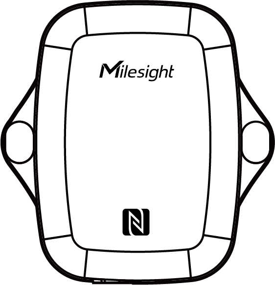 |
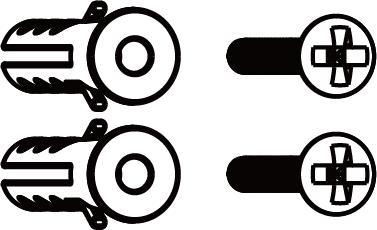 |
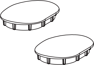 |
| 1 × EM300 Device | 2 × Wall Mounting Kits | 2 × Screw Caps |
 |
 |
|
| 1 × Warranty Card | 1 × Quick Start Card | |
| Accessories Exclusively for EM300-SLD | ||
 |
 |
|
| 1 × 3M Double Sided Tape | 1 × Mounting Screw | |
| Accessories Exclusively for EM300-MCS | ||
 |
 |
|
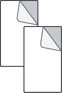
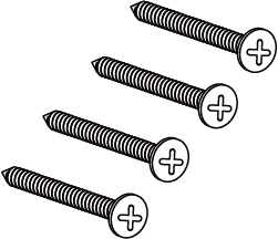
| 2 × 3M Double Sided Tapes | 4 × Mounting Screws | |
Hardware Introduction
Hardware Overview
- EM300-TH
-
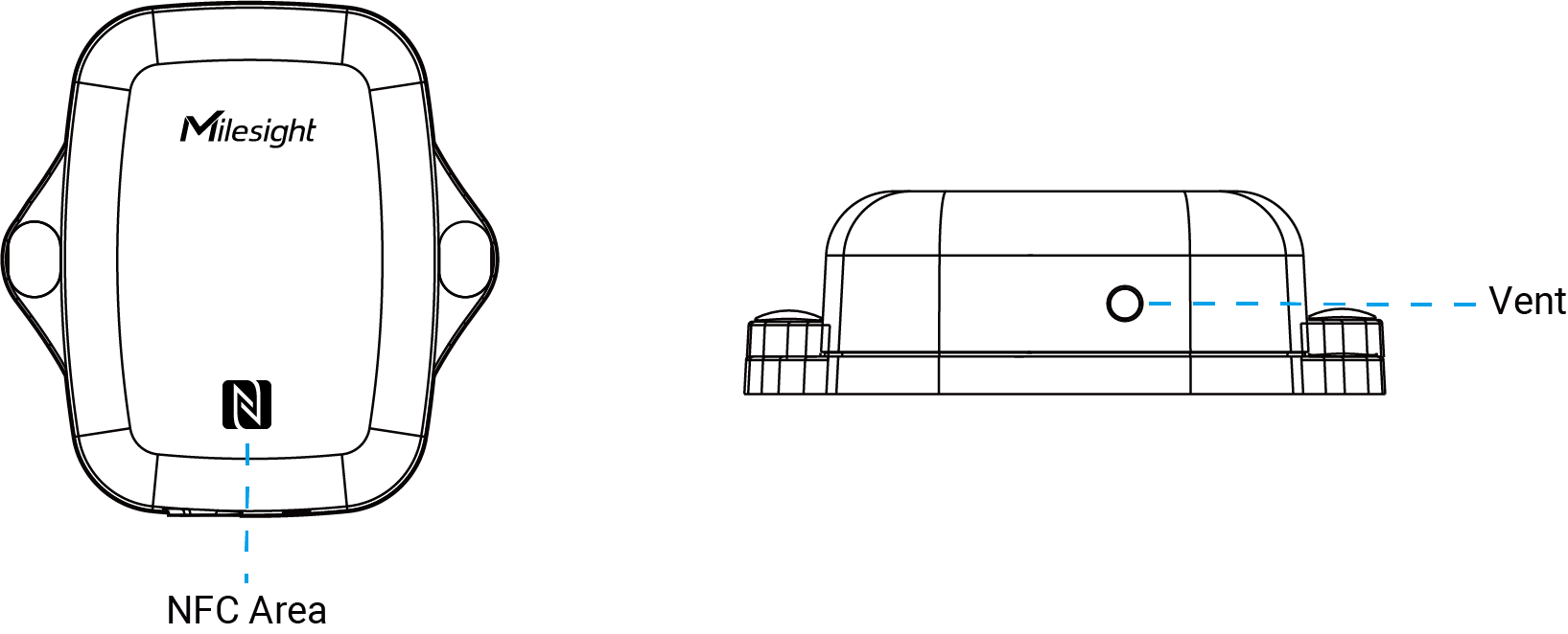
- EM300-MLD
-
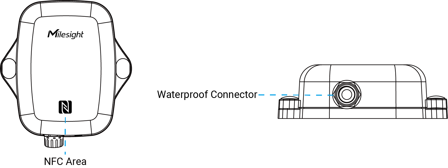
- EM300-SLD/ZLD/MCS/DI
-
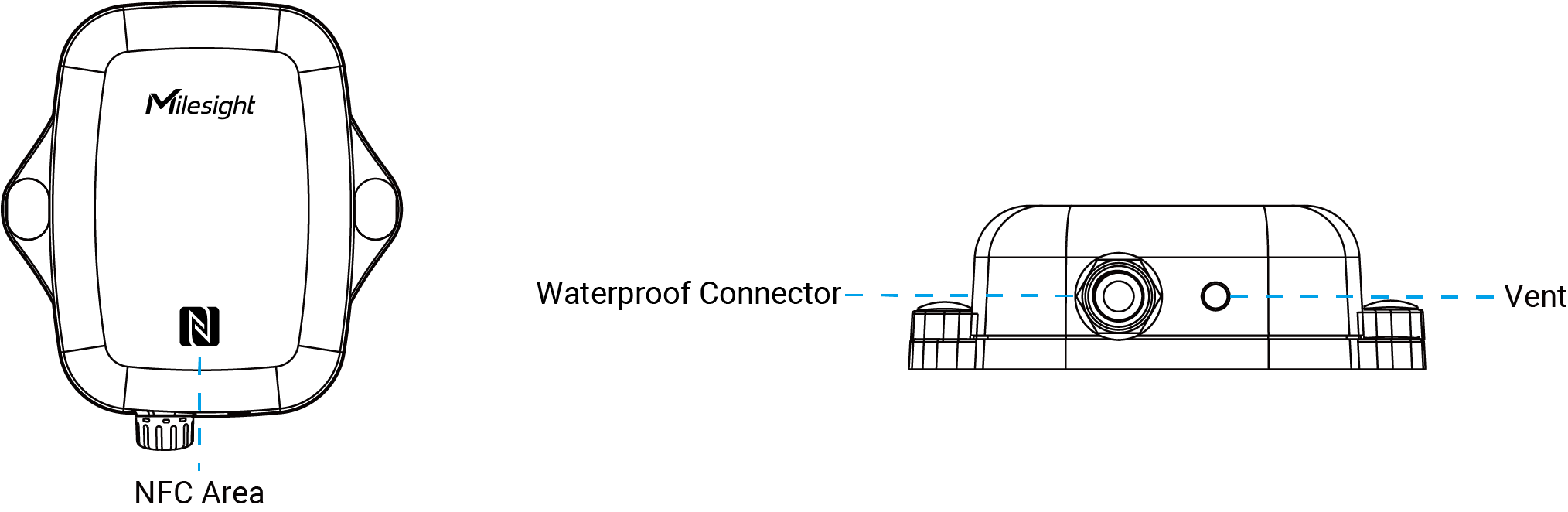
| Part | Description |
|---|---|
| NFC Area | Enables power on/off and wireless configuration via Milesight ToolBox App. |
| Vent | Used to improve the detection accuracy of temperature and humidity. |
| Waterproof Connector | Used to connect an external detection sensor. |
Power Button Descriptions
There is a LED indicator and a power button inside the device for emergency reboot or reset.
| Function | Action | LED Indicator |
|---|---|---|
| Power On |
Press and hold the button for more than 3 seconds. |
Off → On |
| Power Off |
On → Off |
|
| Reset to Factory Default |
Press and hold the button for more than 10 seconds. |
Blinks quickly |
| Check On/Off Status |
Quickly press the power button once. |
Light On: device is on. |
| Light Off: device is off. |
Dimensions
The following figure shows the device dimensions (unit: mm).

Power Supply
The EM300 is available in two versions:
- 4000mAh model (with one built-in battery)
- 8000mAh model (with two built-in batteries)
When the device runs out of power, please refer to the following steps to properly replace the battery.
- Screwdriver
- The device can only be powered by ER18505 Li-SOCl2 battery not alkaline battery.
- Always replace with a new battery. Using the old battery may reduce battery life or lead to inaccurate power level calculations.
- Remove the battery from the device if it is not used for an extended period.
- Do not install 2 batteries on the 4000mAh version, and vice versa. Otherwise, it will cause inaccurate power calculations.
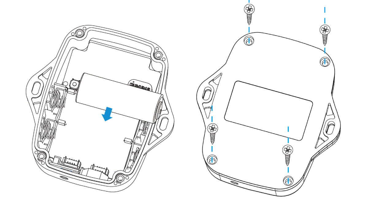
- Remove the back cover using a screwdriver.
-
Replace the new battery correctly, ensuring proper orientation and model compatibility.Tip: To reduce the interference of NFC transmission, it is suggested that the battery be installed in the upper location (see figure).
Hardware Installation
Install the Device
Installation Requirement
Keep the device away from metal objects and obstacles.
Wall Screw Mounting
- Wall Mounting Kits
- Screw Caps
- Electric Drill
-
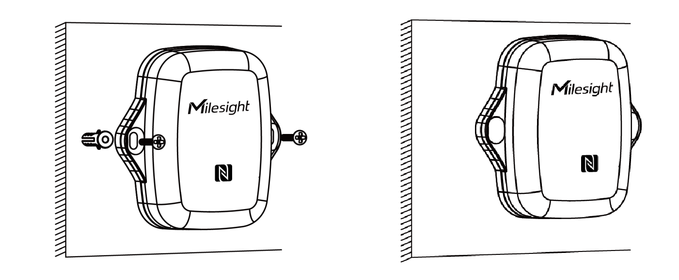
Attach the EM300 device to the wall and mark the two holes on the wall. The connecting line of two holes must be a horizontal line.
-
Drill the holes according to the marks and screw the wall plugs into the wall.
-
Mount the EM300 to the wall via mounting screws.
-
Cover the mounting screws with screw caps.
3M Tape Mounting
- 3M Tape
Requirements:
To ensure the devices are securely installed and prevent them from falling due to adhesive peeling, please strictly adhere to the following requirements.
-
The mounting surface must be dry, smooth, firm, and free of oil, dust, or dirt.
-
Do not mount on rough, damp, dusty, greasy surfaces, or those covered with soft materials such as wallpaper or fabric.
-
Clean the surface with alcohol before mounting; avoid touching the adhesive side.
-
Recommended application temperature: 20~40°C. In low temperatures, pre-warm the tape to approx. 30°C.
-
After mounting, press firmly for at least 30 seconds to ensure full contact.
-
Allow 24 hours of curing time before use.
-
If the surface is unsuitable or long-term use in low temperatures is required, use screw fixing instead.
- Apply 3M tape to the back of the sensor, avoiding contact with the adhesive.
- Remove the liner, position the sensor on a desired surface.
- Press firmly as described above.

Pole Mounting
- Cable-tie
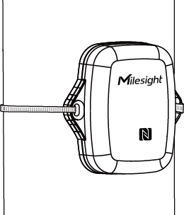
- Pass the cable tie through the mounting holes of the device and wrap the
device around the pole.
Detection Probe Installation (EM300-SLD Only)
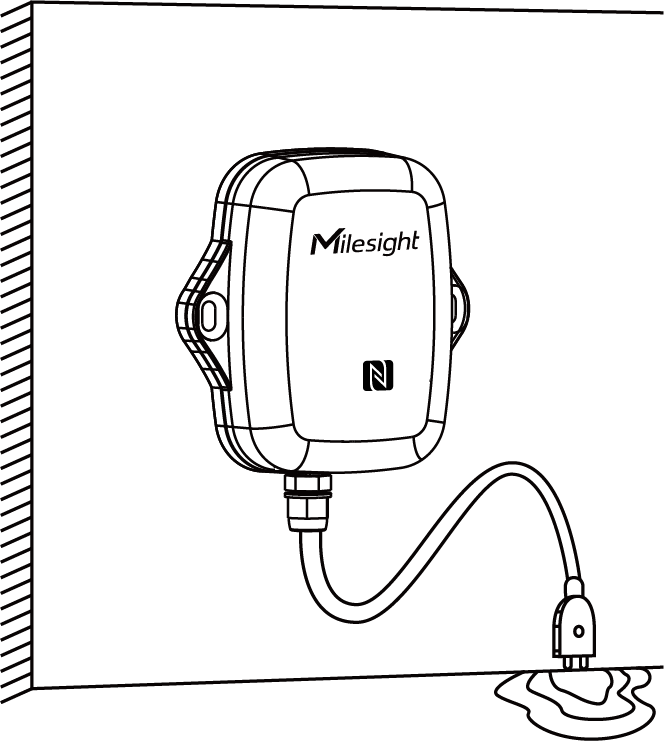
EM300-SLD leak detection probe has two metal pins to detect the water leakage. When the water touches both metal pins at the same time (soaking water length > 2.4 cm), the device will trigger the leakage alarms.
The small probe is suitable for the following sites:
- Narrow spaces or corner areas that only accommodate small detection probes;
- Drain pans, floor drains, pits, etc;
- Locations where water will reach first or accumulate easily when a leak occurs.
The probe supports being secured either with a screw or 3M tape. When installing, ensure the installation surface is smooth and free of debris, and orient two metal pins toward the location where the water may accumulate.
Membrane Installation (EM300-MLD Only)
Installation Locations Requirement:
Usually the membrane can be placed under the electrical appliances (refrigerator, washing machine, etc.), while the EM300-MLD and connector can be fixed on the adjacent wall.
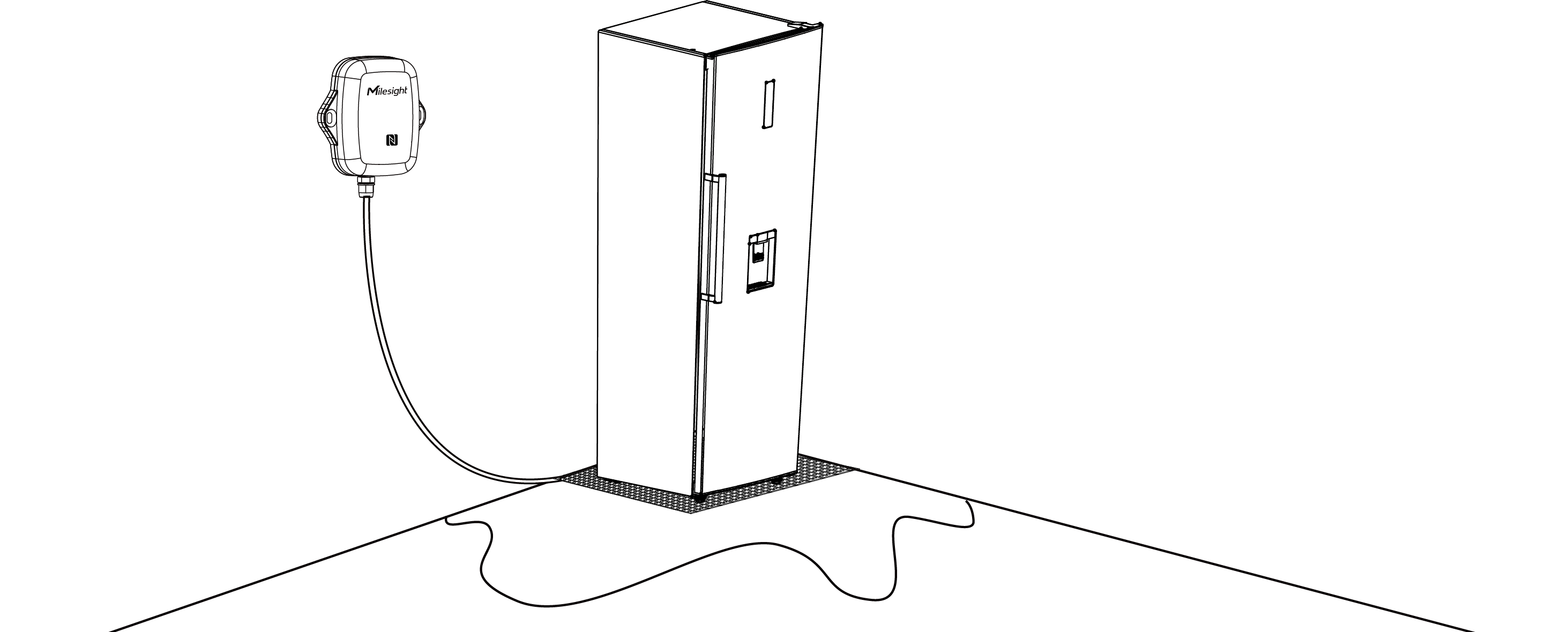
To achieve the best sensitivity, ensure the installation location is a flat and free of debris, dust, or deep gaps. If the membrane needs to be pasted to the installation location, the surfaces should be cleaned and free from dirt, adhesive residue, water drops and other things.
Steps:
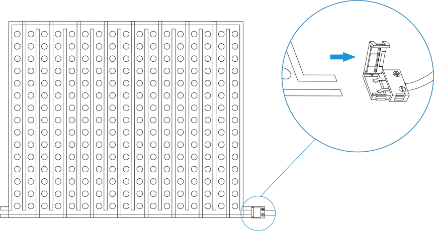
- Connect the membrane to the EM300 device.
- Slide one of the tabs sticking out from the membrane into the connector of EM300-MLD device.
- Ensure the black lines touch the two metal parts of the connector.
- Restore the connector cover back to fix the membrane into the device.
- Install the Membrane.
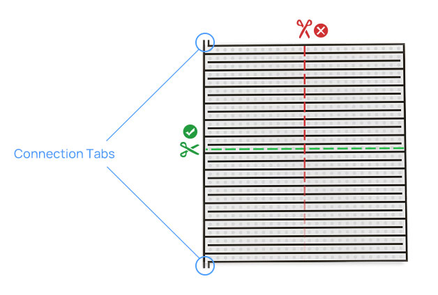
- Cut the membrane to suit the detection area or keep the whole
membrane without cutting. It is necessary to cut the membrane in the
direction shown below to avoid disconnecting the black lines.Note: One membrane has two connection tabs and can be cut into two pieces for two EM300-MLD devices. If you only use one tab and the other tab is useless, you can also cut it.
- Remove the protective film on the detection side.
-
Put the membrane on the installation location, ensure the detection side touches the detection area or detection object, and make sure the membrane is placed flat without crimping.
Besides, you can tear the other side to paste the membrane to the wall via 3M tape.
- Cut the membrane to suit the detection area or keep the whole
membrane without cutting. It is necessary to cut the membrane in the
direction shown below to avoid disconnecting the black lines.
Maintenance:
Cable Installation (EM300-ZLD Only)
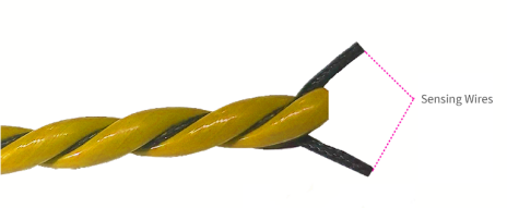
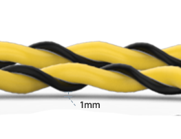
EM300-ZLD sensing cable consists of two black sensing wires and polyethylene. When water covers the cable and touches the sensing wires (soaking water length ≥ 3 cm and depth ≥ 1mm), the device will trigger the leakage alarms. It's important to note that this sensing cable does not pinpoint the exact location of the leakage.
Installation Locations Requirement:
- The sensing cable can be wrapped around pipes, routed along to walls or placed on the floors.
- Ensure that the surfaces of the installation location are clean and free of debris, dirt, adhesive residues, water droplets, and other contaminants.
-
Installation location should be away from foot traffic, sharp objects and areas where heavy items may roll or drop onto the cable.
-
Keep the cable away from air-conditioning outlet or moist places to avoid false alarms.
- The connectors should be kept away from the water to avoid error alarm report.
- Connect the connector on one end of the sensing cable to the EM300-ZLD device
connector, then tighten the connectors. Note: The sensing cable comes with only one connector and does not support the connection of additional sensing cables to extend the detection length. If you need to expand the length, please contact Milesight to customize the cable length or purchase a sensing cable with connectors on both ends to replace the default one.
- Install the sensing cable at the designated installation locations.Note:
- It is not suggested to fix the cable with glue which may damage the cable.
- Do not wrap the cable with metal objects to avoid the interference.
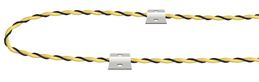
- Install cable to floors/walls: Attach the sensing cable to the
installation location without a gap and fix it tightly with cable clips.
Do not fix the cable with glue or metal which may affect the detection
sensitivity.
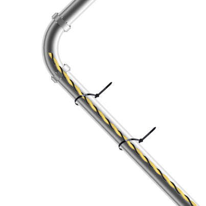
- Install cable to pipes: Wrap the sensing cable around the pipe
and fix it tightly with cable ties. When installing, the cable should
not be twisted or coiled.
After removing the cable from the leakage location, dry the cable and ensure the leakage status back to “No Leak”. The cable can be reused in other places.
Magnet Installation (EM300-MCS Only)
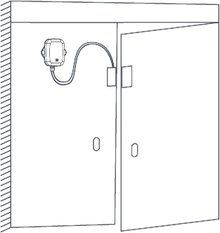
- Doors, windows and any facilities that need open/close detection.
- Do not install the magnets to or close to iron objects.
Steps:
- Put the two magnet parts to the target location and mark the location as
needed. To ensure the best detection, both parts should be aligned and the
holes of the magnets should face outward.
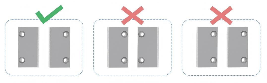
- Fix the two magnet parts with 3M tape or screws.

Access the Device Using NFC
This section describes how to access the device using NFC.
Prerequisites: The device is powered by internal or external power source.
Steps:
- Download Milesight ToolBox app from Google Play or Apple Store.
- Enable the NFC function on the smart phone.
- Launch ToolBox.
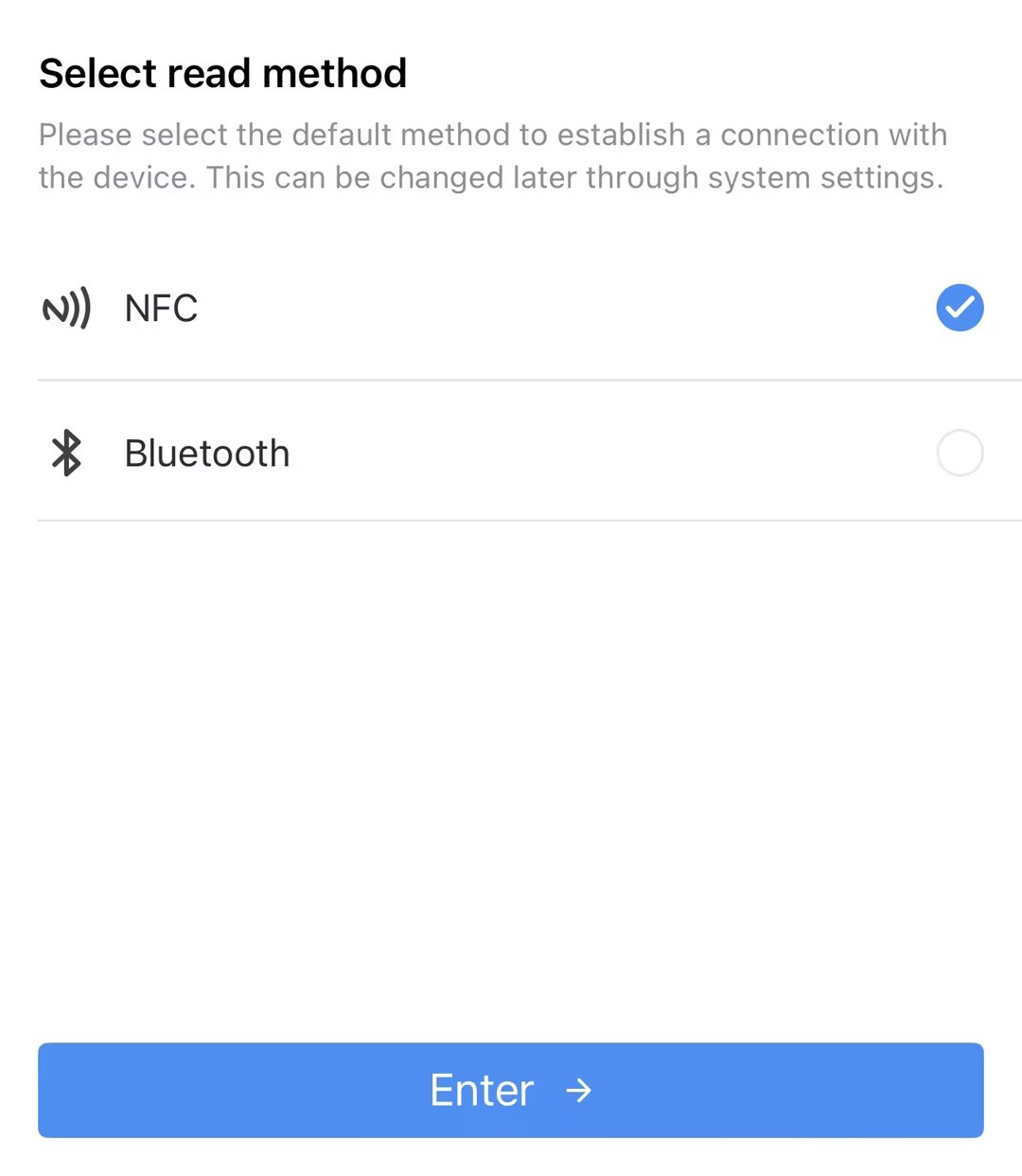
- Upon initial launch, the following page will appear. Select NFC
and click Enter.
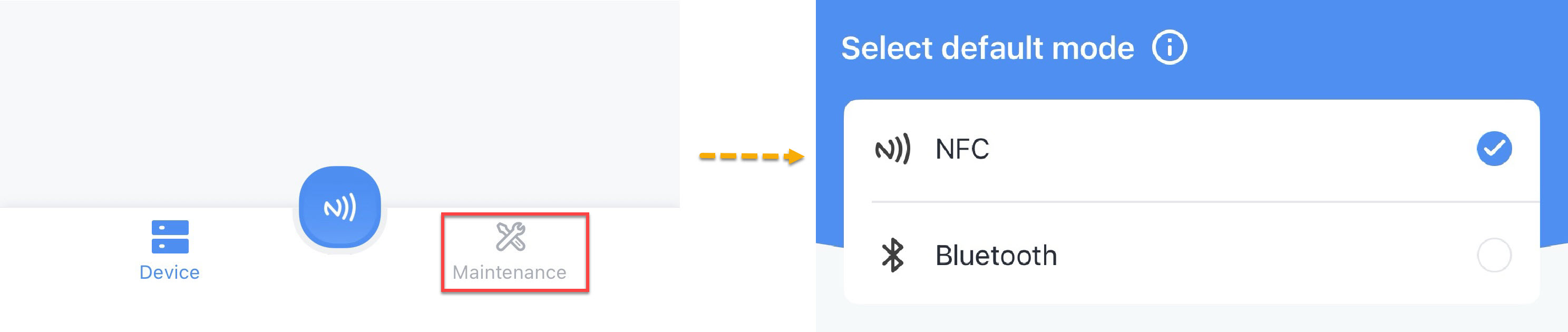
- Upon subsequent launches, Click Maintenance on the home page, and
then select NFC.
- Upon initial launch, the following page will appear. Select NFC
and click Enter.
- (Optional) To locate the NFC detection areas of the phone and the device, click Can't find the NFC location.
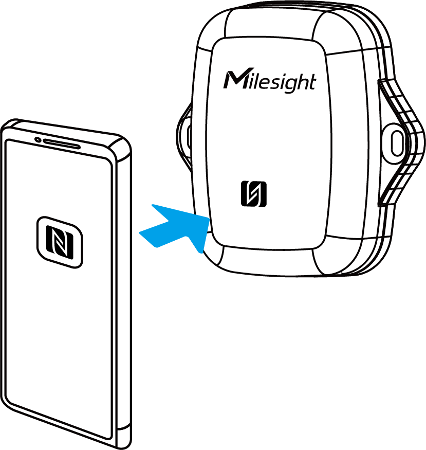
- Put the NFC detection area of the phone close to the NFC antenna of the device.Tip: It is recommended to remove the phone case.
- Click
 . If the device is recognized successfully, the homepage is
displayed. Troubleshooting: If read fails, move the phone away and reposition it close to the sensor to try again.For a description of the homepage, refer to the following table.
. If the device is recognized successfully, the homepage is
displayed. Troubleshooting: If read fails, move the phone away and reposition it close to the sensor to try again.For a description of the homepage, refer to the following table.Item Description Basic Information Show basic device information and sync the device time. Setting Set the device and network parameters. 
Import, add, export or delete a template. 
Select language, show NFC positions, check App version, etc..
FCC Statement
Any changes or modifications not expressly approved by the party responsible for compliance could void the user’s authority to operate the equipment. This device complies with part 15 of the FCC Rules. Operation is subject to the following two conditions:
- This device may not cause harmful interference, and.
- This device must accept any interference received, including interference that may cause undesired operation.
- Reorient or relocate the receiving antenna.
- Increase the separation between the equipment and receiver.
- Connect the equipment into an outlet on a circuit different from that to which the receiver is connected.
- Consult the dealer or an experienced radio/TV technician for help.
FCC Radiation Exposure Statement:
This equipment complies with FCC radiation exposure limits set forth for an uncontrolled environment. This equipment should be installed and operated with minimum distance 20cm between the radiator& your body. This transmitter must not be co-located or operating in conjunction with any other antenna or transmitter.
Related Resource
For more information, please refer to Milesight Document Center.