Installation Prerequisites
Choose an Installation Position
- Avoid installing the device against the wall. Keep the
following minimum distances between the device and the wall:
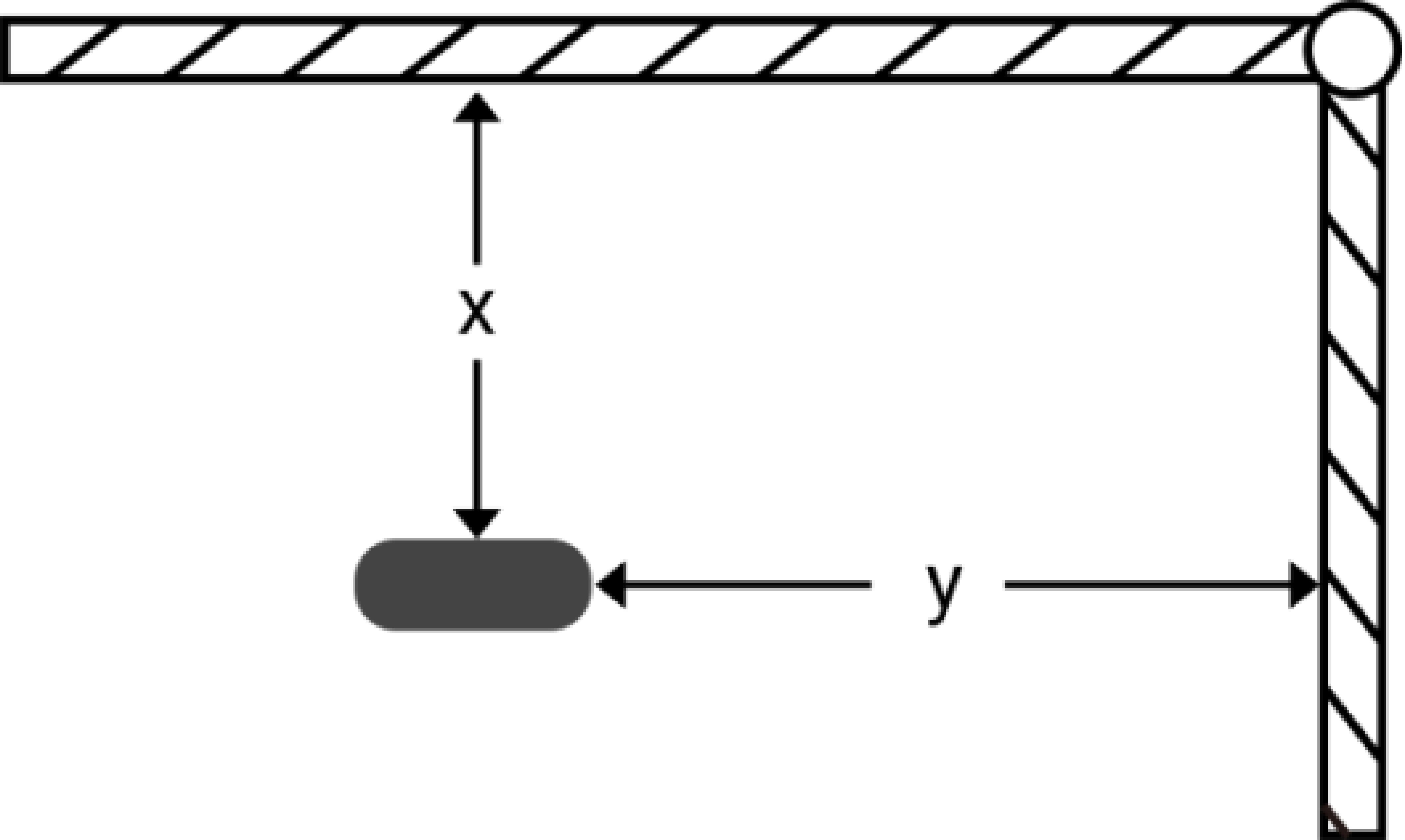
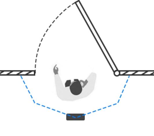
Condition Standard Environment Dark Carpet/Floor (need to set noise filtering to the maximum level) Normal imaging x > 50 cm, y > 60 cm x > 50 cm, y > 75 cm Normal counting x > 50 cm, y > 50 cm x > 50 cm, y > 50 cm - When installing above a swinging door, keep the door normally open. If the door
must stay closed, install the device on the opposite side, at least 30 cm
away from the door's movement path.
- Keep the ToF sensor facing downward and avoid tilted installation.
- Ensure no objects block the ToF light within a 30 cm radius in front of the device.
- Avoid direct Infrared LED light in the detection area.
- Do not install the device close to glass or mirror surfaces.
Check Environment Conditions
- Avoid 940 nm light sources, which may cause incorrect counting.
- Direct outdoor sunlight on the monitoring area has no effect. However, avoid mirrored reflections that direct sunlight onto the ToF sensor.
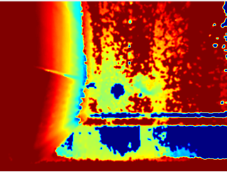
- Keep the live view free of obstacles. Obstacles may cause the device imaging to
appear abnormally red and affect counting accuracy. Adjust the noise filtering
level according to the actual image: the harder it is to distinguish targets,
the higher the filter value should be.
Estimate Detection Coverage
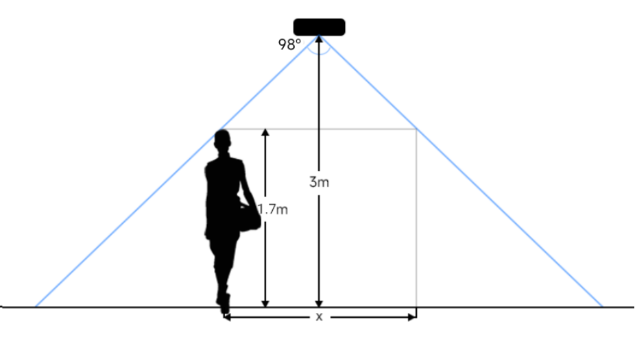
The monitored area is the full range visible to the device (shown on the dashboard). The detection area is the smaller region within it where the device can actually detect changes in the number of people. The detection area depends on the device's field of view angle, installation height, and target height.
| Parameter | Description | Value |
|---|---|---|
| Δd | Distance measurement error | 0.035 m |
| hmax | Maximum pedestrian height | Example: 1.8 m |
| h | Average pedestrian height | Example: 1.7 m |
| H | Installation height | hmax+d+Δd ≤ H ≤ 3.5 m |
| α | ToF horizontal field of view angle | 98° |
| β | ToF vertical field of view angle | 80° |
| x | Detection range length | 2 × tan(α/2) × (H−h) |
| y | Detection range width | 2 × tan(β/2) × (H−h) |
Installation height limits: Maximum=3.5m. Minimum = hmax + d + Δd.
For example, with hmax = 1.8 m: 1.8 + 0.5 + 0.035 = 2.335 m.
Conclusion: 2.235 m ≤ H ≤ 3.5mThe following illustration uses an installation height of 3 m and a target height of 1.7 m as an example:
| Installation Height (m) | Monitored Area (m2) | Detection Area (m2) |
|---|---|---|
| 2.5 | 5.75 × 4.20 | 1.84 × 1.34 |
| 2.6 | 5.98 × 4.36 | 2.07 × 1.51 |
| 2.7 | 6.21 × 4.53 | 2.30 × 1.68 |
| 2.8 | 6.44 × 4.70 | 2.53 × 1.85 |
| 2.9 | 6.67 × 4.87 | 2.76 × 2.01 |
| 3.0 | 6.90 × 5.03 | 2.99 × 2.18 |
| 3.1 | 7.13 × 5.20 | 3.22 × 2.35 |
| 3.2 | 7.36 × 5.37 | 3.45 × 2.52 |
| 3.3 | 7.59 × 5.54 | 3.68 × 2.69 |
| 3.4 | 7.82 × 5.71 | 3.91 × 2.85 |
| 3.5 | 8.05 × 5.87 | 4.14 × 3.02 |
Plan Multi-Device Coverage
When the area you need to monitor exceeds a single device's detection range, use multiple devices side by side to extend coverage. The devices stitch their detection ranges together to act as one unified monitoring zone. Use the following parameters to calculate how many devices are required for your space.
| Parameter | Description | Value |
|---|---|---|
| Δd | Distance measurement error | 0.035 m |
| hmax | Maximum pedestrian height | Example: 1.8 m |
| h | Average pedestrian height | Example: 1.7 m |
| H | Installation height | hmax+d+Δd ≤ H ≤ 3.5 m |
| α | ToF horizontal field of view angle | 98° |
| β | ToF vertical field of view angle | 80° |
| x | Detection range length of each device | x = 2 × tan(α/2) × (H−h) |
| y | Detection range width of each device | y = 2 × tan(β/2) × (H−h) |
| a | Number of devices required along the coverage length | Coverage length ÷ x, round to the nearest integer based on deployment requirements |
| b | Number of devices required along the coverage width | Coverage width ÷ y, round to the nearest integer based on deployment requirements |
Example: For a coverage area of 6 m × 3 m (length × width) with VS133-P devices installed at 3 m height (H) and 1.7 m target height (h):
x = 2.99 m, a = Coverage length ÷ x = 6 ÷ 2.99 ≈ 2.00≈ 2 devices
y = 2.18 m, b = Coverage width ÷ y = 3 ÷ 2.18 ≈ 1.38≈ 2 devices
Conclusion: 2 × 2 = 4 devices are required for complete coverage of the 6 m × 3 m area.