Wiring and Installation
This chapter describes the controller terminals, HVAC wiring diagrams and the device installation steps.
Before Installation
CAUTION: The controller is designed for 24VAC
systems only. Do not install it on high-voltage, high-current, or millivolt
systems!
Prerequisites
- Confirm that the controller is compatible with the target HVAC system.
- If an NTC sensor or DI device will be connected, complete the compatibility check before installation.
- If the controller and the WT401 thermostat communicate through Bluetooth, keep the two devices within 10 meters of each other.
- Make sure the controller is located within the LoRaWAN® gateway's communication range. Do not install it inside a fully enclosed metal object cabinet or behind large metal obstructions.
- Check the default accessories in the box.
Wire Terminal Descriptions
The terminal names below are the actual controller terminals. The listed colors apply only to the supplied wire harness. Identify existing HVAC wires by terminal label, not by wire color.
| Terminal | Harness Wire Color | Description |
|---|---|---|
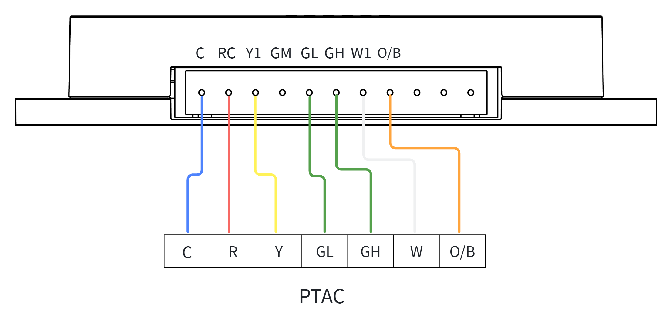
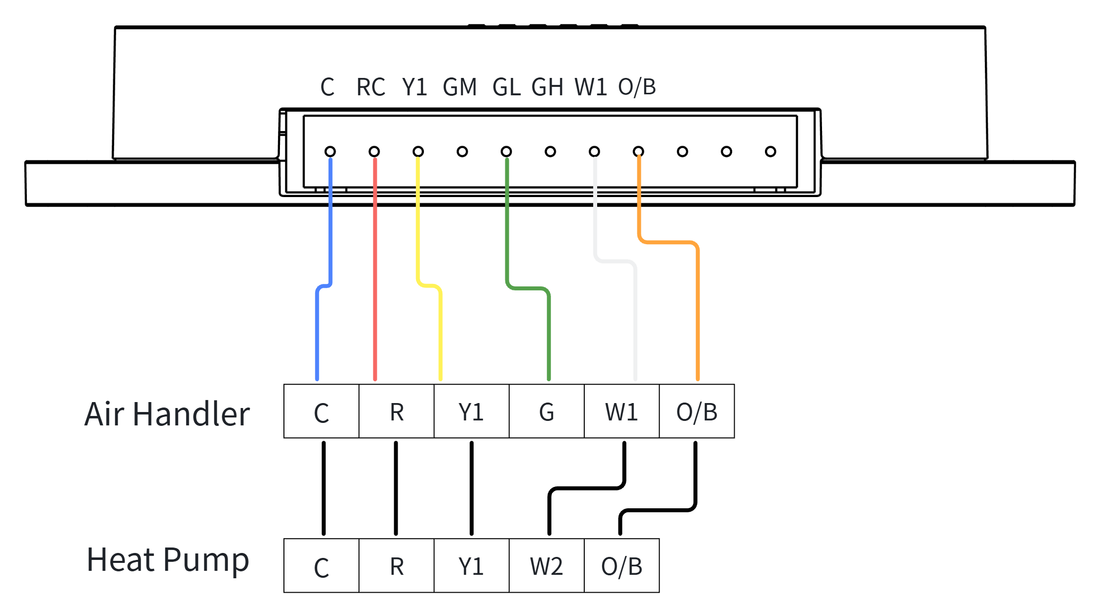
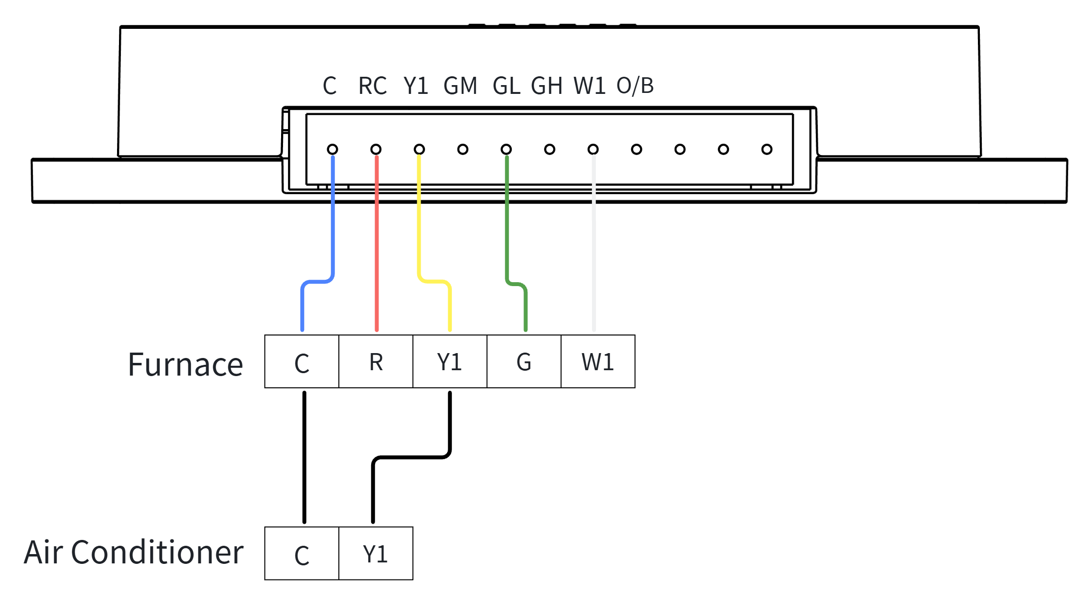
| C | Blue | Common wire of 24 VAC power. If no C wire, check if this wire is labelled as other names (like B). |
| RC | Red | Heating or cooling power wire. |
| Y1 | Yellow | In conventional systems, Y/Y1 controls the 1-stage cooling. In heat-pump systems, Y1/Y1 controls the 1-stage compressor for cooling/heating. |
| GM | Green | Medium-speed fan. In multiple-fan system, connect G2 or GM to this wire. |
| GL | Green | Low-speed fan. In multiple-fan system, connect G1 or GL to this wire. If there is only G wire, connect to this wire as well. |
| GH | Green | High-speed fan. In multiple-fan system, connect G3 or GH to this wire. |
| W1 | White | In conventional systems, W/W1 controls the 1-stage heating. In heat-pump systems with auxiliary heat, W/W1 controls the 1-stage auxiliary heat. |
| O/B | Orange | In heat pumps, O/B controls the reversing valve to switch between heating and cooling. If there is only one O wire or B wire, connect this wire to O/B of the controller. |
Wiring Diagrams
Select the wiring diagram that matches the target HVAC system.
Wiring for PTAC
Wiring for Heat Pumps
Wiring for Conventional Systems
Installation Procedure
Step 1. Connect the Controller to the HVAC System
Prerequisites: Wire Harness, Screwdriver, Electrical Tapes
Steps:
- Power off the HVAC system by using the master switch or circuit breaker.
- To confirm power is off, adjust the temperature on the
current thermostat and wait for a few minutes. If the system does not respond
accordingly, the power is shut off successfully.Warning: Failure to follow these steps may result in personal injury and/or death from electric shock.
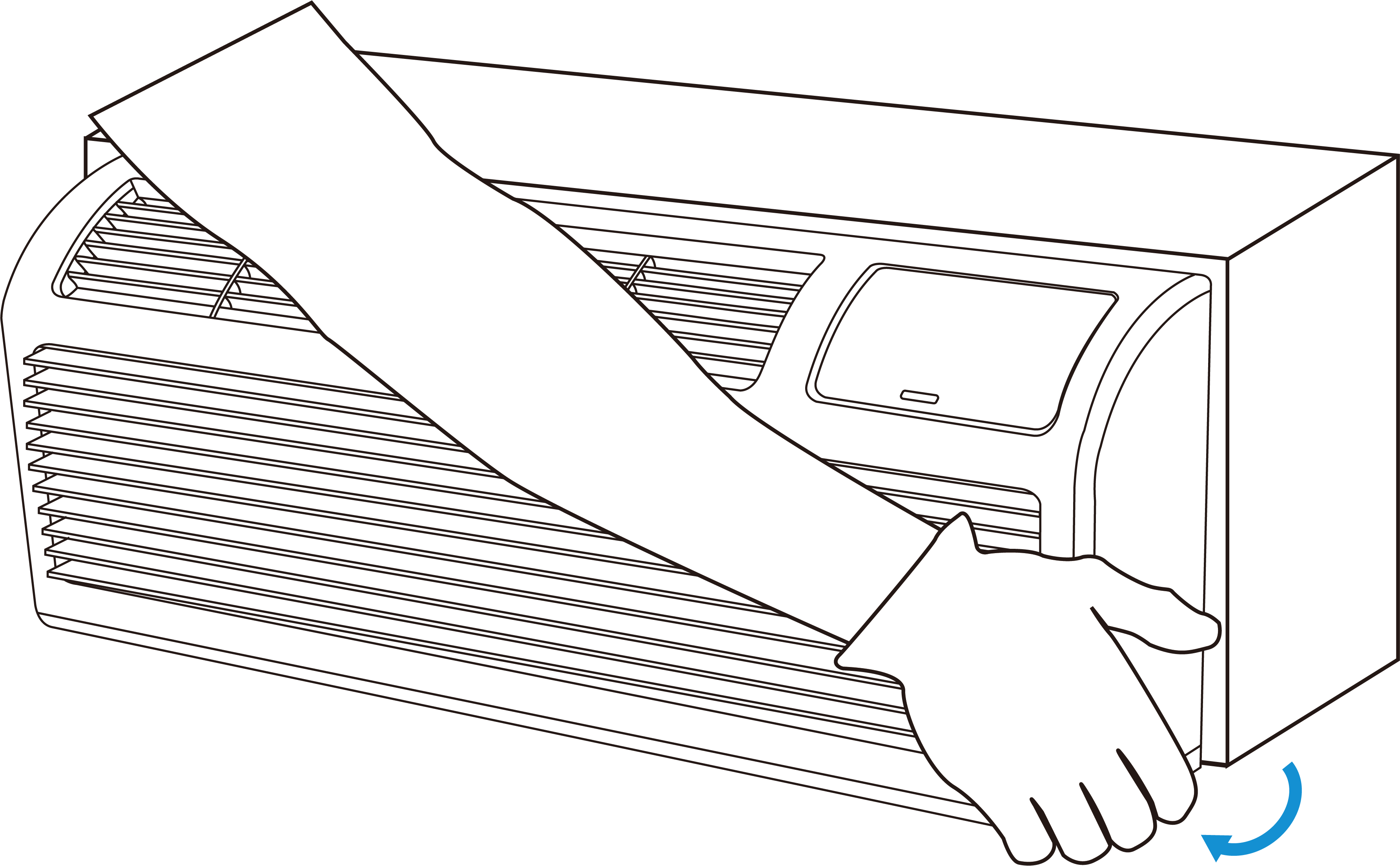
- Remove the cover of the HVAC system.
- Locate the HVAC control terminal block. If it is connected to a thermostat or
controller, disconnect the wires from the old device.CAUTION: If the system is labeled with L1 and L2, or with high-voltage indicators like 110V, 120V, or 240V, it means the controller is not compatible with this system. DO NOT CONTINUE INSTALLTION.
- Strip a suitable length of insulation from the wire harness, then fasten it to
the HVAC control terminal block according to the applicable wiring
diagram.
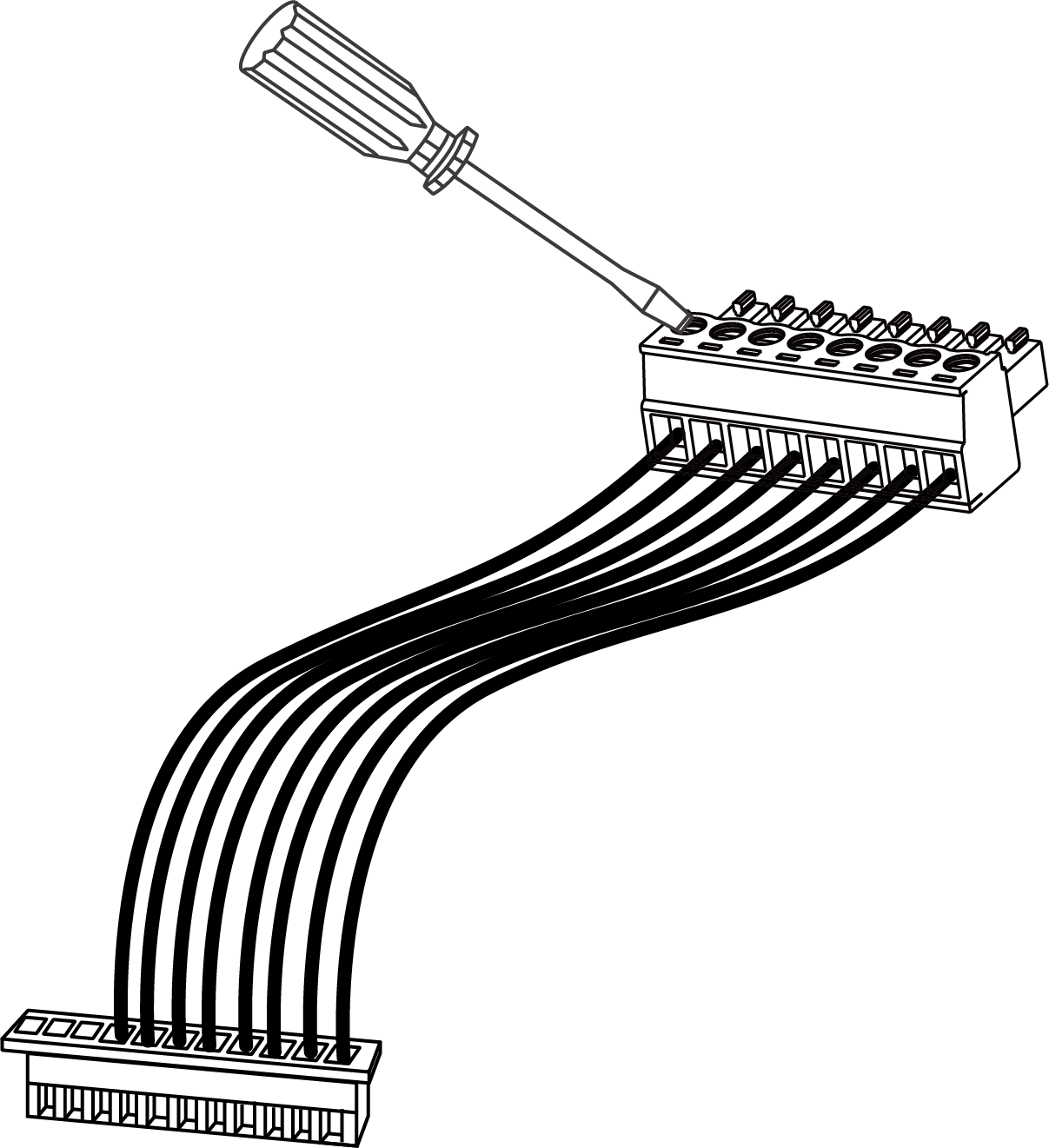
- Secure and insulate any excess wire with electrical tape.
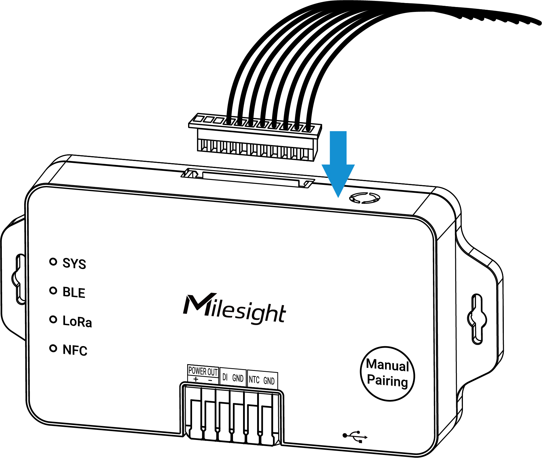
- Install the wire harness to the controller.
Step 2. Connect Controller to External Sensors (Optional)
Prerequisites:
- Confirm that the external sensor or dry-contact device is compatible with the controller.
- Ensure the wire diameter of the sensors complies with AWG 24-16.
- Strip 8-9 mm of insulation from the ends of the sensor's wires.
Steps:
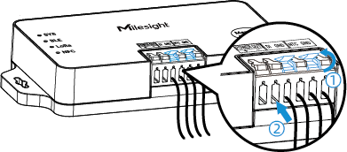
- Lift the small levers of the corresponding interface.
- Push the stripped wires fully into the terminal openings.
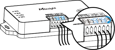
- Close the levers to activate the internal spring clamps.
- Gently pull the wires to ensure they are securely fixed to the controller.
Step 3. Install the Controller
The controller supports multiple mounting options. Select the appropriate method for
the installation location.
- 3M Tape Mounting
- Requirements: To ensure the devices are securely installed and prevent falling due to adhesive failure, please strictly adhere to the following requirements.
- The mounting surface must be dry, smooth, solid, and free of oil, dust, and debris.
- Do not mount on rough, damp, dusty, greasy surfaces, nor those covered with soft materials such as wallpaper or fabric.
- Clean the surface with alcohol before installation; avoid touching the adhesive side.
- Recommended application temperature: 20-40°C. In low temperatures, pre-warm the tape to approximately 30°C.
- Allow 24 hours of curing time before use.
- If the surface is unsuitable or long-term use in low temperatures is required, use screw mounting instead.
Prerequisites: 3M Tape
Steps:- Apply 3M tape to the back of the device, avoiding touching the
adhesive side with your fingers.
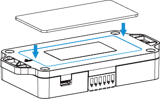
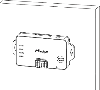
- Remove the liner and position the device to the target surface.
- Press firmly for at least 30 seconds to ensure full
adhesion.
- Wall Screw Mounting
- Requirements:
- The wall structure shall be sufficiently solid and stable to ensure firm screw fixation and overall mounting stability.
- Screw mounting positions must avoid internal wall electrical wiring, water pipes and other concealed utilities to prevent structural damage and potential safety hazards.
Prerequisites: Wall Screw Mount Sets, Screwdriver, Pencil, Electric Drill (15/64" or 1/4" drill bits)
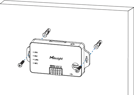
Steps:- Drill two holes in the wall aligned with the wall-mount holes of the controller.
- Insert the wall plugs into the drilled holes.
- Fasten the device to the wall plugs with the supplied wall mounting
screws.
- Magnetic Mounting (Optional)
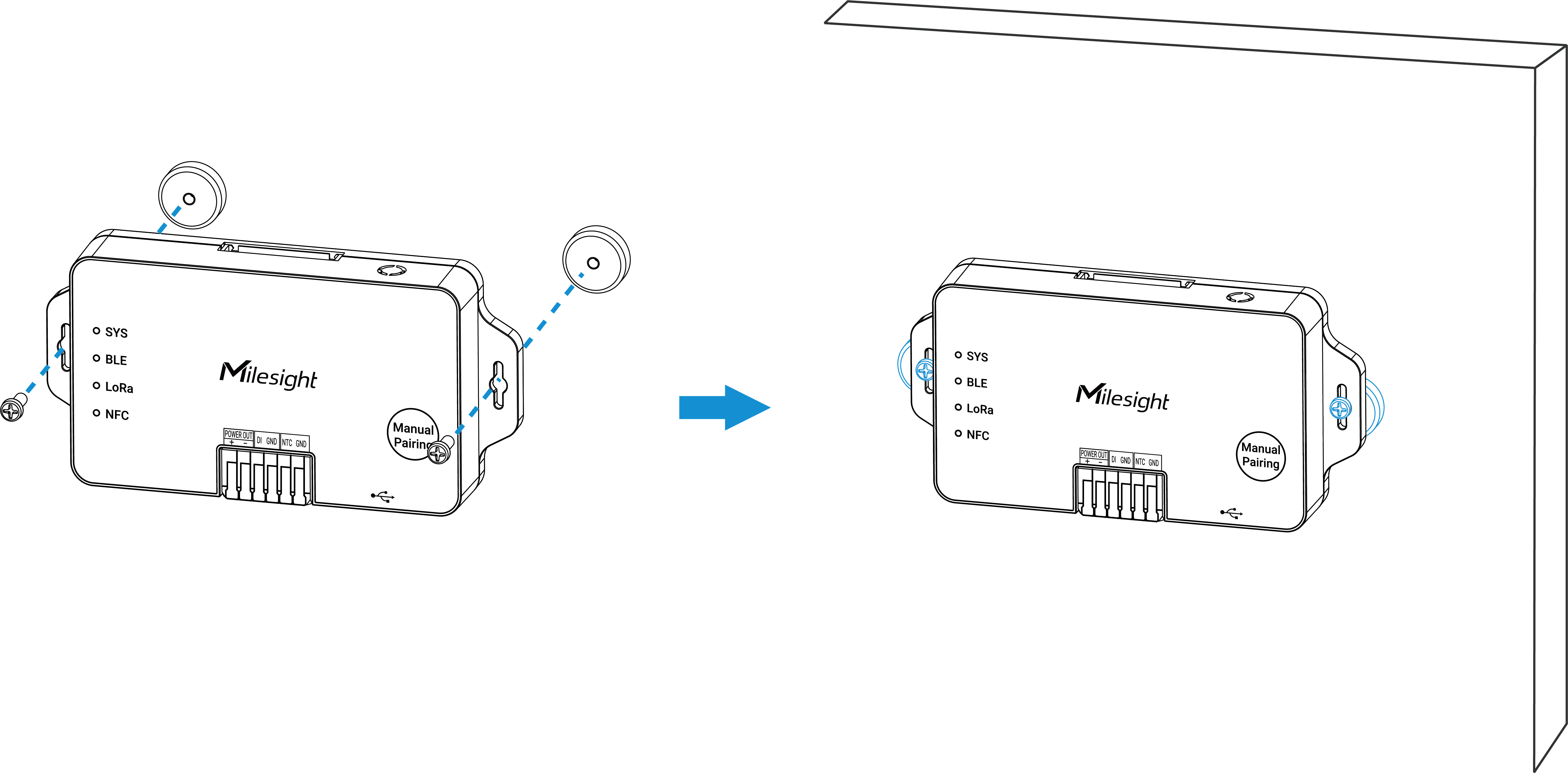
- The device can be mounted to a magnetic surface after screwing the magnetic
nuts. Contact Milesight for more details about this accessory.
Step 4. Test the Controller
- Test the controller with the following steps.
- Power on the HVAC system.
- Switch HVAC system control permission to external control. Refer to the corresponding HVAC system guide for the required steps.
- Check whether the SYS indicator is steadily on to confirm that the controller is powered on.
- Check whether the LoRa indicator is steadily on to confirm if the controller has joined the network.
- Connect to a WT401 thermostat and check if WT401 can control the controller.
- Restore the HVAC system cover.