Hardware Components
Main Components
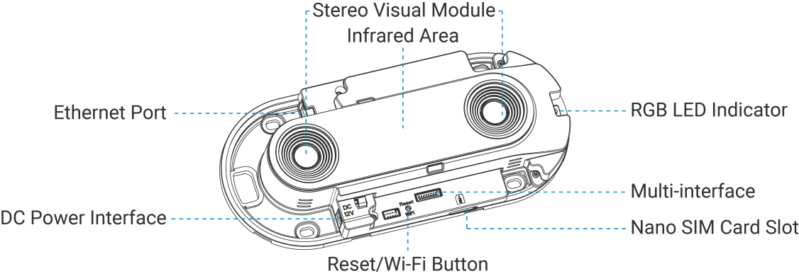
For the description of each component, refer to the following
table:
| No | Name | Description |
|---|---|---|
| 1 | DC Power Interface | Provides a power input for the device by connecting to an external DC power adapter. |
| 2 | Ethernet Port/PoE (PoE Version Only) | Provides data communication and multi-device stitching capability. When Power over Ethernet/PoE (PoE version only)is supported, this port can also power the device. |
| 3 | Stereo Visual Module | It is a dual-camera module that captures and processes stereoscopic images. |
| 4 | Infrared Area | Provides night vision capability by emitting invisible infrared light to illuminate the scene. |
| 5 | RGB LED Indicator | Provides visual status indications through a multi-color LED. |
| 6 | Multi-interface | Equips with Digital Input/Output, RS485 (under development) and UART(Used to connect VA05 UWB Staff Detection Anchor; Hardware v2.x supported only) interfaces. For wiring details, refer to Wiring Diagram. |
| 7 | Nano SIM Card Slot (Cellular Version Only) | Slot for inserting a Nano-SIM card to establish a cellular network connection. |
| 8 | Reset/Wi-Fi Button | See Button Patterns. |
Power Button and LED Indicators
The functions of the button and the corresponding LED indicator status, refer to the following table.
| Function | Action | LED Indicator |
|---|---|---|
| Enable/Disable Wi-Fi | Long press the button for 3 seconds. | Enable/Disable: The blue light
blinks for 3 seconds.
|
| Reset the device | Long press the button for 10 seconds. | The green light blinks until the reset process is completed. |
| Module or algorithm detection error | / | The red light is on. |
Wiring Diagram
The following figure shows the wiring diagram.Figure 1. DI/DO

- DI: By default, two connected contacts = low level, two disconnected contacts = high level.
- DO: Loads up to 1A@24V DC.
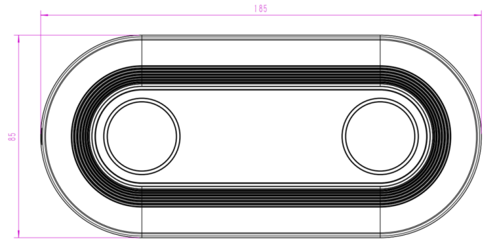
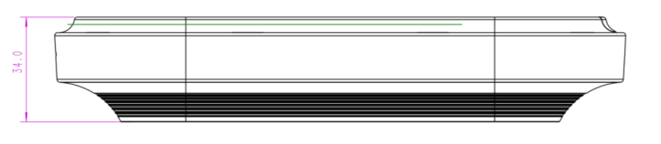
Dimensions
The following figure shows the device dimensions (unit: mm).