UC722 Quick Start Guide
Overview
Safety Instructions
These instructions are provided to ensure correct product operation and to prevent personal injury or property damage. Milesight shall not be held liable for any loss or damage arising from failure to comply with the instructions in this guide.
- Do not place the device close to objects with naked flames.
- Do not place the device where the temperature is below/above the operating range.
- Installation must be performed by qualified professionals.
- All electrical work must be carried out by licensed electricians in accordance with local regulations.
- Ensure that the power supplies to the air conditioning system and controller are disconnected before wiring.
- Do not disassemble, modify, or repair this product yourself.
- The device must never be subjected to shocks or impacts.
- Do not connect communication terminals to high-voltage terminals.
Packing List
 |
 |
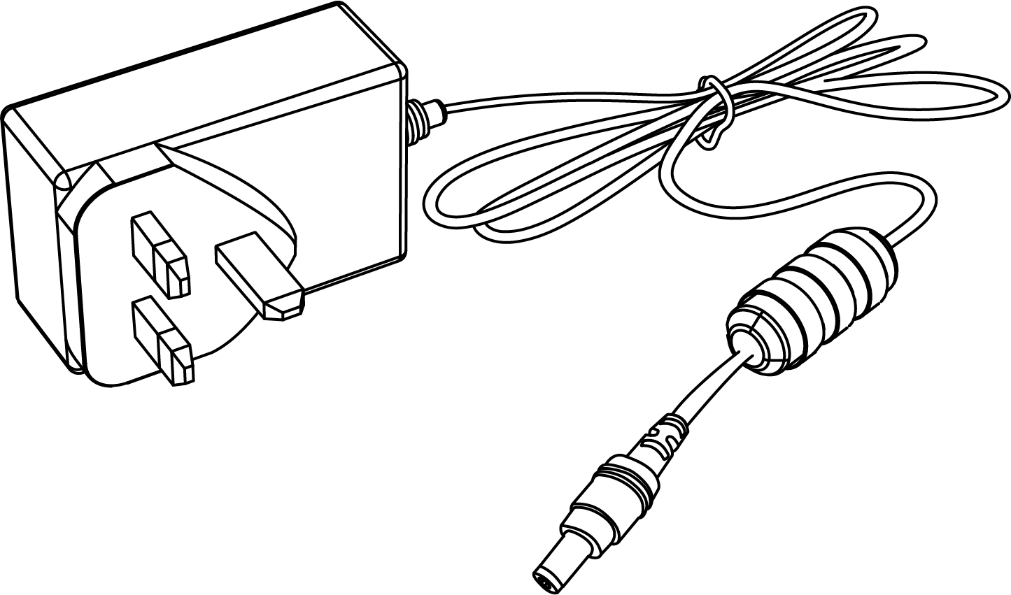 |
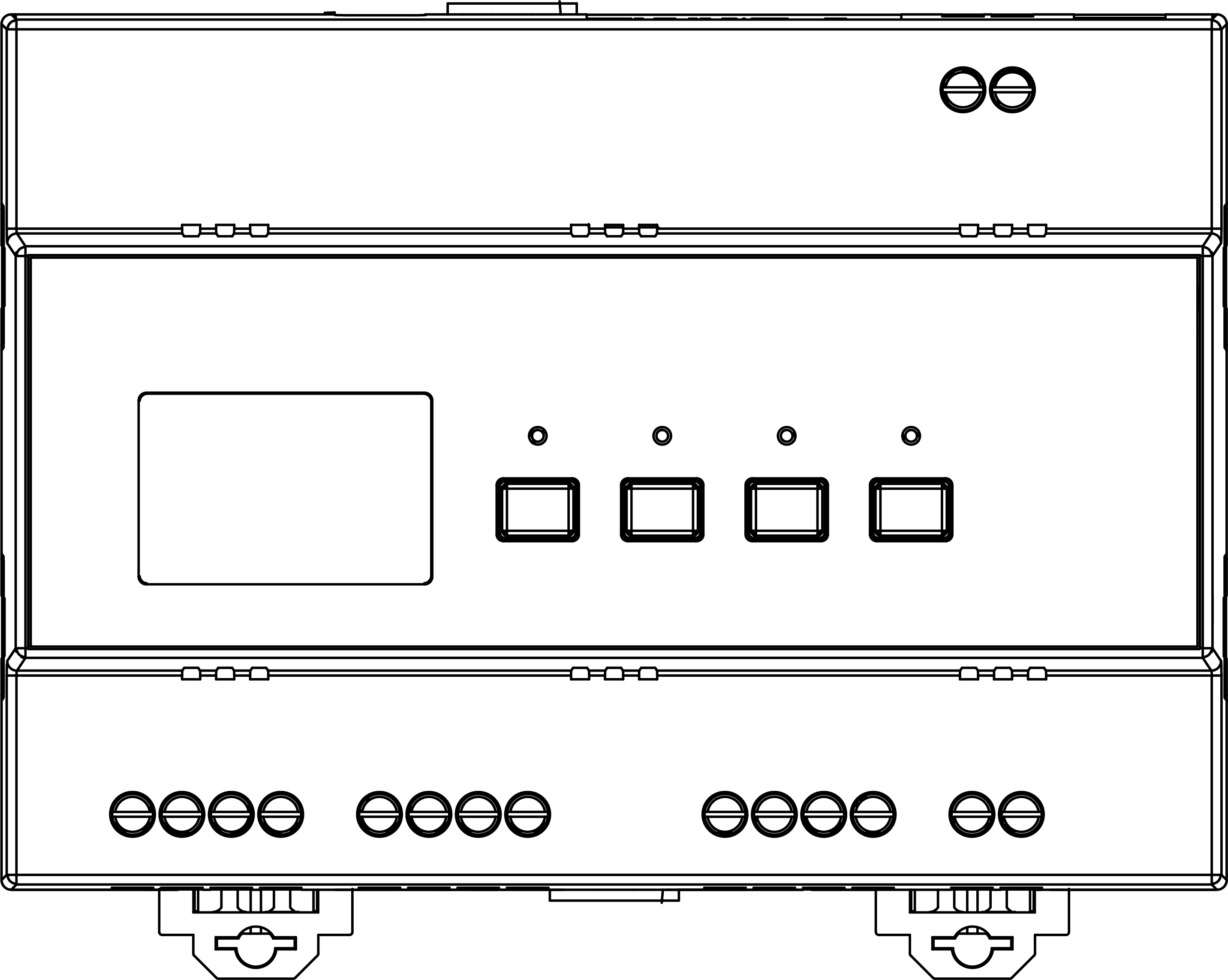
| 1 × VRF System Controller | 4 × Colour‑coding Resistors | 1 × AC/DC 12V/2A Power Converter |
 |
 |
|
| 1 × Warranty Card | 1 × Quick Guide Card |
Hardware Introduction
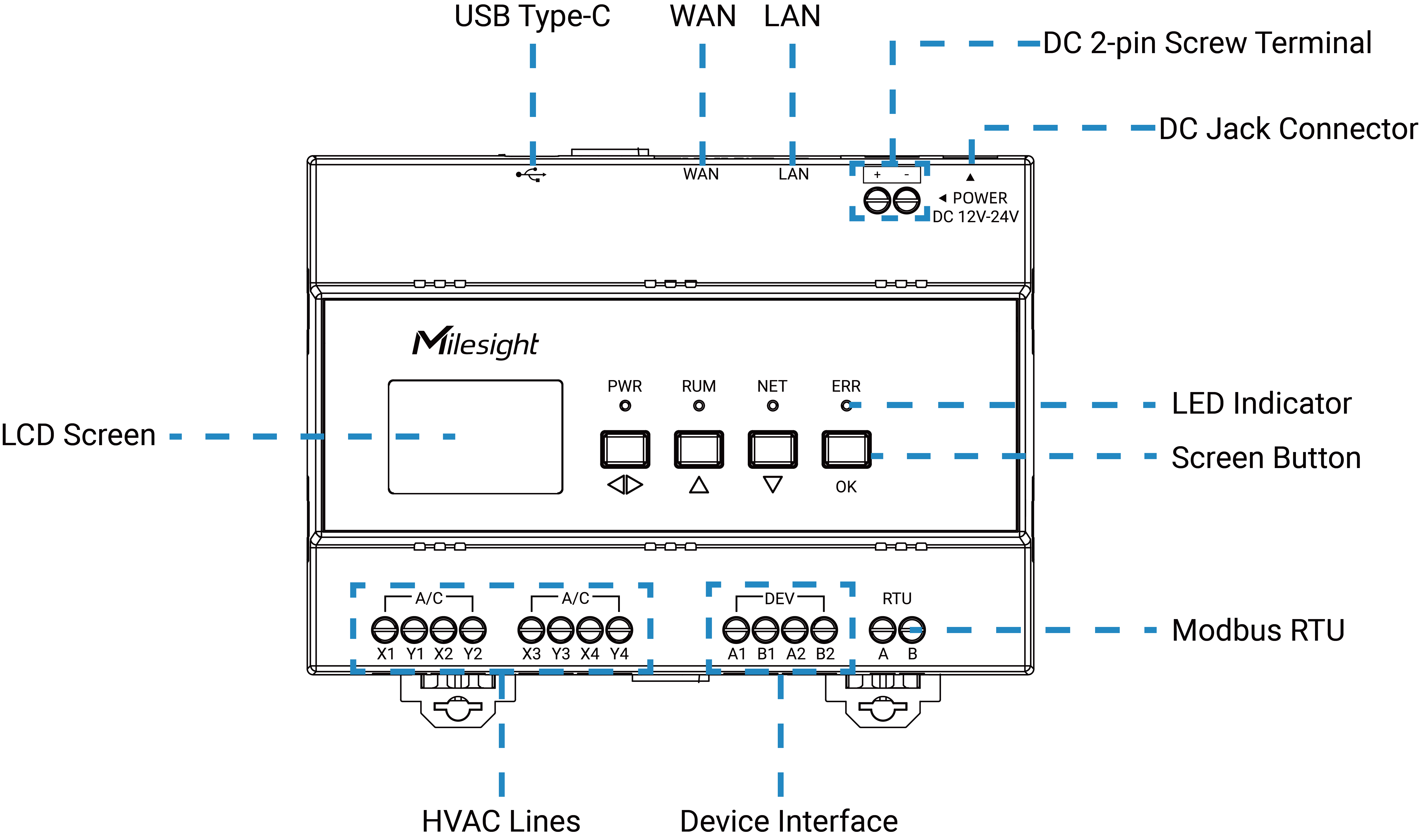
Hardware Overview
| Part | Description |
|---|---|
| WAN | Used to connect to Ethernet, supports remote servers accessing the controller via Modbus TCP or JSON. |
| LAN | Used to connect to local network, supports local servers accessing the controller via Modbus TCP or JSON. |
| DC Jack Connector | The interface for powering the device. |
| DC 2-pin Screw Terminal | |
| LED Indicator | Indicates the device operating status. For more details,refer to LED Patterns. |
| LCD Screen | Displays the device's basic information, interface status, and operational status. For more details, refer to Screen Description. |
| Screen Button | Used for status viewing and page navigation. For more details, refer to Screen Button Description. |
| HVAC Channel | Used to connect to the outdoor master unit of the VRF system. The connection is non-polarized. |
| Device Interface | Used to connect to the electricity meter (Reserved). |
| RTU Interface | External output interface of the controller based on the Modbus RTU protocol. |
| USB Type-C (Reserved) | Reserved for debugging. |
LED Patterns
| LED | Status | Description |
|---|---|---|
| PWR | Off | Device is not powered or is faulty |
| On | Device is powered normally | |
| RUN | Blinks | System is working well |
| Off/On | System malfunctions | |
| NET | Blinks | Network is connected |
| Off | Network is not connected | |
| ERR | Off | No air conditioning fault |
| On | Air conditioning fault |
Screen Description
After the device is powered on, the screen will show all the detected units and their statuses.
| Page | Description |
|---|---|
| Host Information |
|
| Network Setting |
|
| AC Data Overview |
|
|
|
| Meter Information (Reserved) |
|
| Bluetooth (Reserved) |
|
Screen Button Description
| Icon | Description |
|---|---|
 |
Navigates to the next menu level. |
 |
Switches to the previous/next page. |
 |
Switches the items in the page. |
 |
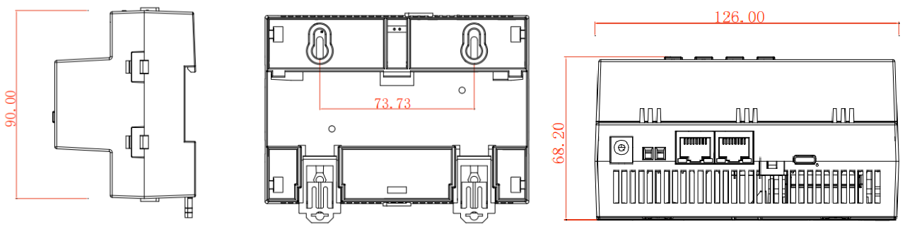
Dimensions
Install the Device
Prerequisite
- Verify that the VRF system has been commissioned and operates normally.
- Identify the HVAC brand, number of independent VRF systems, and required communication terminals. If unsure, refer to the Appendix for details.
Step 1. Connect the Controller to VRF System
The VRF system connects to the controller via a 2-core shielded twisted-pair cable.
Before Wiring
- Power off the VRF system.
- Use a 2-core shielded twisted-pair cable, ≥ 0.75 mm².
- Keep the total communication cable length within 1000 m.
- The LAN cable length within 80 m.
- Ensure the enclosure is properly Class D grounded.
Wiring Precautions
To minimize signal interference:
- Keep the communication cable at least 15 cm away from other HVAC communication cables.
- Keep at least 30 cm away from other wiring.
- If these distances cannot be maintained, route the cable through a metal conduit and ground one end.
Wiring Steps
-
Locate the communication terminal: Open the outdoor unit panel and locate the communication terminal on the outdoor master unit.
-
Route the communication cable: Run the shielded twisted-pair cable from the outdoor master unit to the controller. Secure the cable with conduit or cable-ties where required..
-
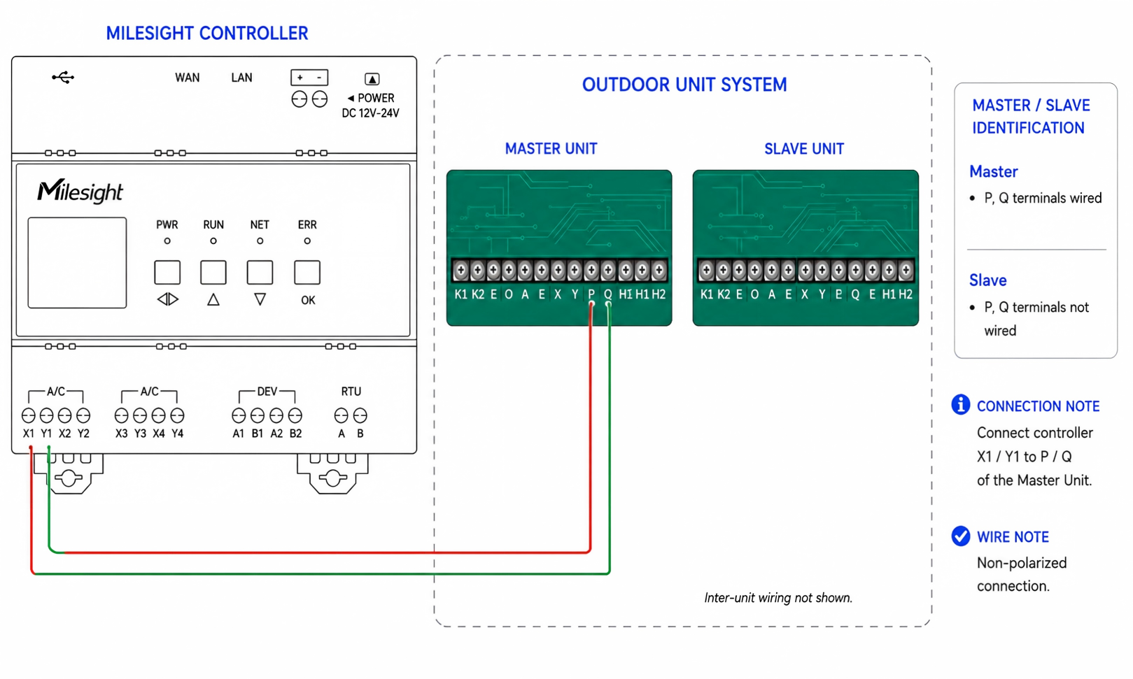
Connect the outdoor unit: Connect one end of the cable to the communication terminal on the outdoor master unit.
-
Connect the controller: Connect the other end to the corresponding HVAC channel on the controller.
For multiple VRF systems, connect each outdoor master unit to an independent UC722 channel.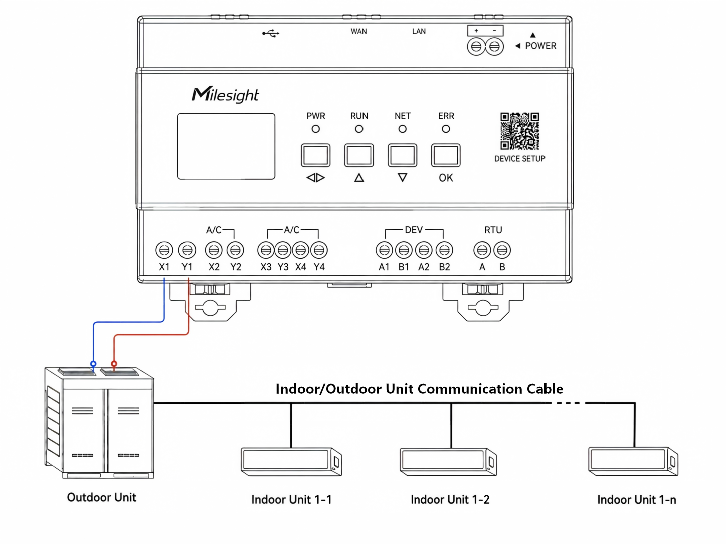
Step 2. Install the Controller
Installation Requirements
- Leave at least 3 cm clearance below the device to allow Ethernet cable routing.
- Install the device indoors, away from direct sunlight, rain, high humidity, or dusty environments.
- Ensure adequate space around the device for heat dissipation.
- If mounted in a metal enclosure, the enclosure must be properly grounded (Class D protective earth).
- If outdoor installation is unavoidable, use a waterproof enclosure and ensure reliable grounding.
- Mount the device below 2 meters above ground for easy operation and screen viewing.
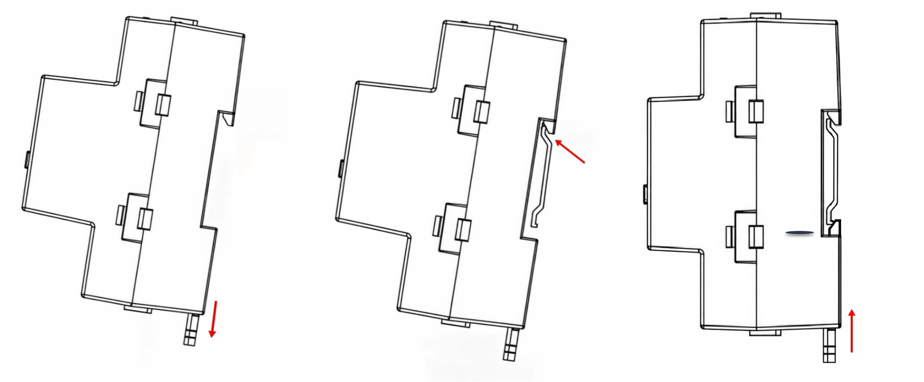
- DIN Rail Mounting
-
Steps:
- Fit the device’s top-side clips into the upper edge of the DIN rail.
- Press the lower side of the device gently until it locks onto the DIN rail.
- Make sure the gateway is firmly fixed.
- Wall Mounting
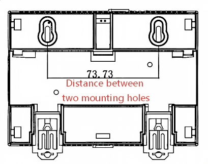
- Requirements:
- The wall structure shall be sufficiently solid and stable to ensure firm screw fixation and overall mounting stability.
- Screw mounting positions must avoid internal wall electrical wiring, water pipes and other concealed utilities to prevent structural damage and potential safety hazards.
-
Steps:
- Using the wall-mounting holes on the back of the device as a reference, mark the mounting-hole positions on the wall.
- Drill the holes, then install the wall plugs and screws.
- Hang the device on the screws and ensure that it is level and
securely mounted.
Step 3. Install the Circuit Breaker and Connect Power
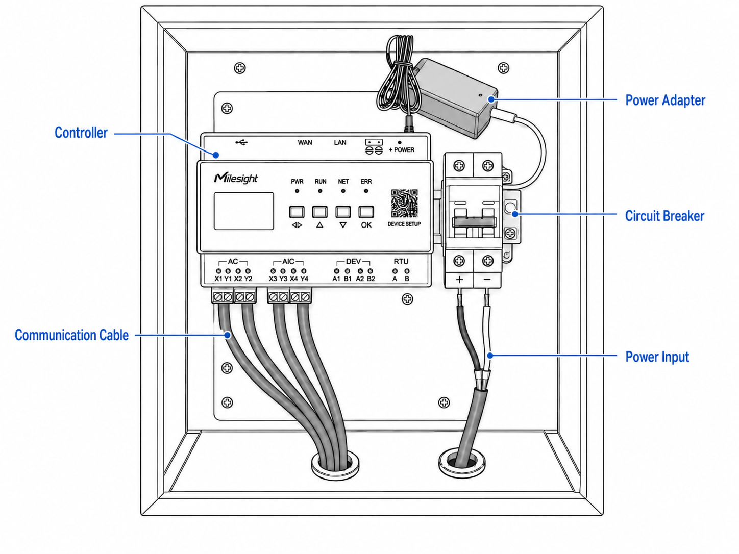
Steps:
- Mount the circuit breaker securely on the DIN rail.
- Connect to a power supply to the input side of the circuit breaker.
- Connect the output side of the circuit breaker to the power adapter.
- Check that all power connections are secure before powering on.
Step 4. Power On the Controller
The controller supports DC power input via a DC jack or 2-pin terminal. It is recommended to use the provided power supply or a reliable DC 12 V power adapter.
Steps:
- Connect the power adapter input to the output terminals of the circuit breaker.
- Insert the DC barrel plug into the controller’s DC power jack
-
Observe the LED indicators.
-
PWR on → Power supply is normal
-
RUN blinking → System has started up normally
-
-
Check whether the LCD screen displays properly.
Getting Started
Step 1. Log in to Controller Web GUI
The device can be configured through the web GUI accessible over Ethernet port.
The default IP address of the device is 192.168.2.251.
- Connect the LAN port of the device to your computer using a network cable.
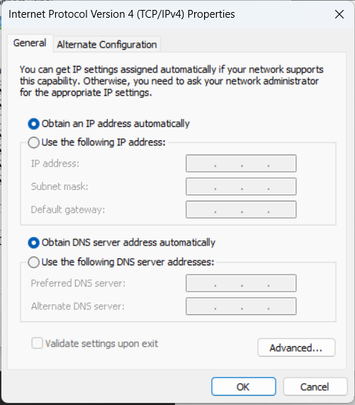
- Configure the IP address of your computer, ensuring it is on the same subnet as
the device. Take Windows 10 as an example:
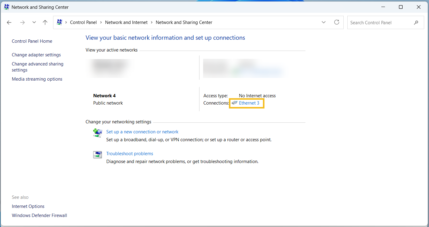
- Navigate to Control Panel > Network and Internet > Network and
Sharing Center and select “Ethernet” (It may have a
different name).
- Navigate to Properties > Internet Protocol Version 4 (TCP/IPv4)
Properties, then select Use the following IP address
to manually assign a static IP address, such as
192.168.2.201/255.255.255.0.
- Open a web browser (Chrome is recommended) and enter the static IP address of the device to access the web GUI.
- Navigate to Control Panel > Network and Internet > Network and
Sharing Center and select “Ethernet” (It may have a
different name).
- Log in to the web GUI using the default credentials.
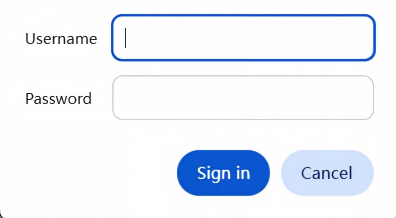
Item Default Username admin Password admin56789*
Step 2. Configure the WAN settings
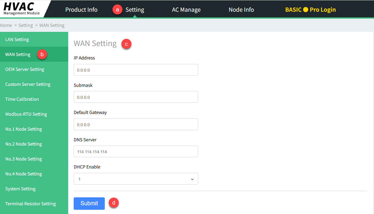
It is necessary to configure the WAN to enable devices to access the network.
- Click Setting > WAN Setting to access the configuration page.
- Enter the related parameters and click Submit to save configuration.
- Connect the WAN port to an active Ethernet cable with network access.
- On the Device LCD screen, select the Network Setting page and enter
WAN Setting page to verify that the displayed IP address matches the
configured value.
Step 3. Calibrate the Device Time
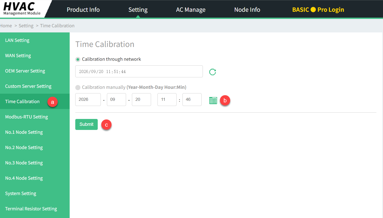
To ensure data accuracy, it is recommended to manually calibrate the time after logging in.
- Enter the Time Calibration interface under the Setting menu.
-
Select Calibration Manually, then enter the time manually.
- Click Submit to apply the changes.
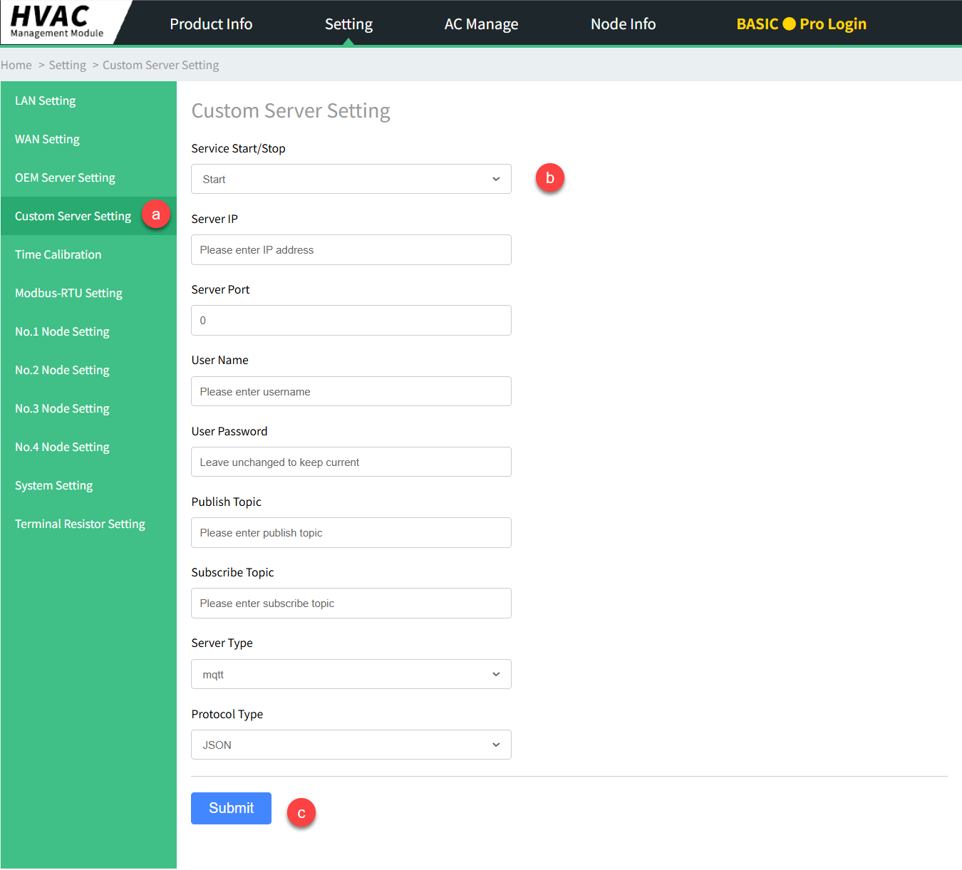
Step 4. Configure the Customer Server Setting
- Navigate to the Custom Server Setting interface under the Setting menu.
- Enter the relevant configuration details provided by the server.
- After configuration is complete, click Submit.
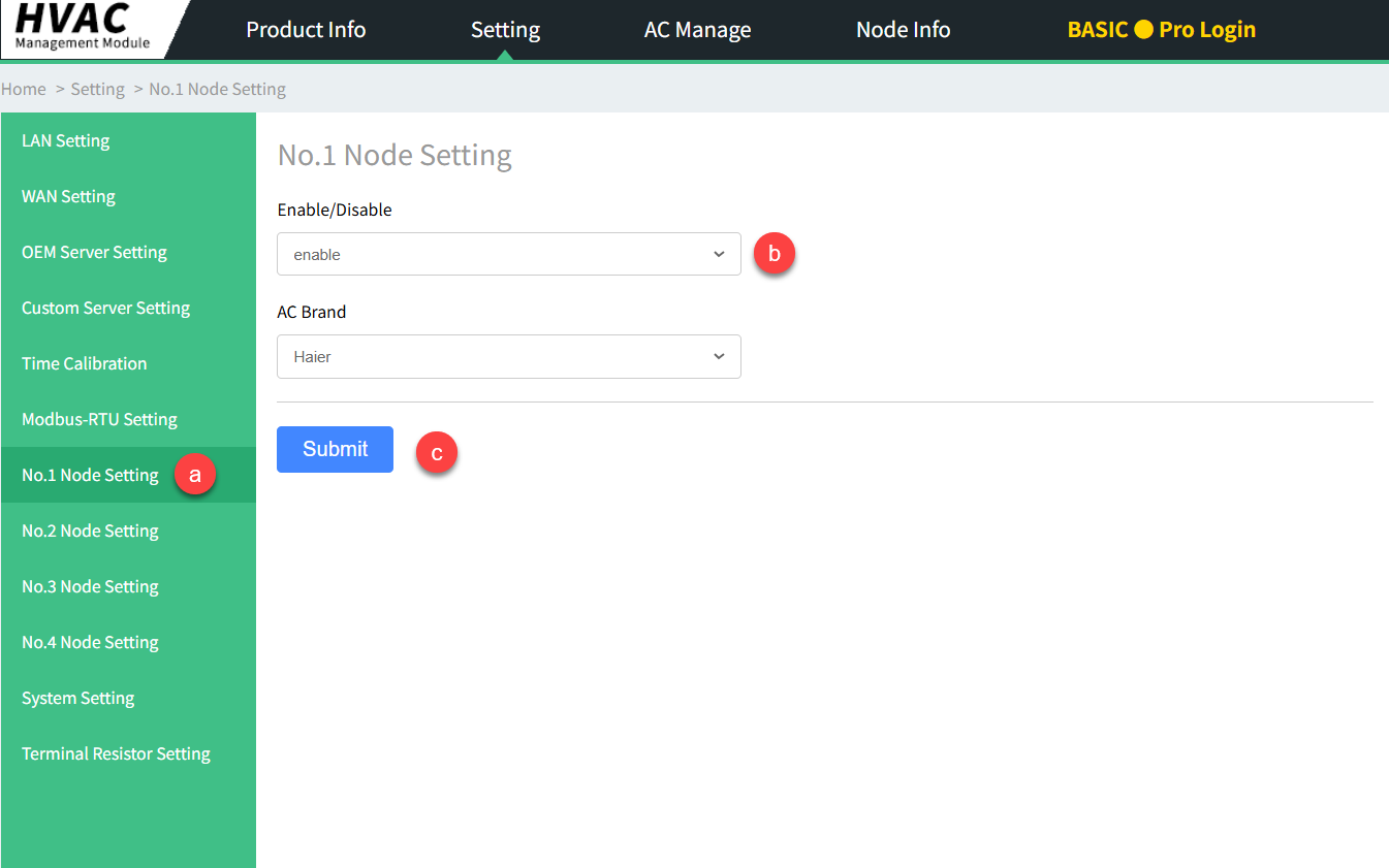
Step 5. Set the Air Conditioner Brand
- Click Setting > No.x Node Setting to access the configuration page.
- Enable the channel.
- In the AC Brand field, select the actual brand of the air conditioner.
- After confirming the selection, click Submit to apply the
change.
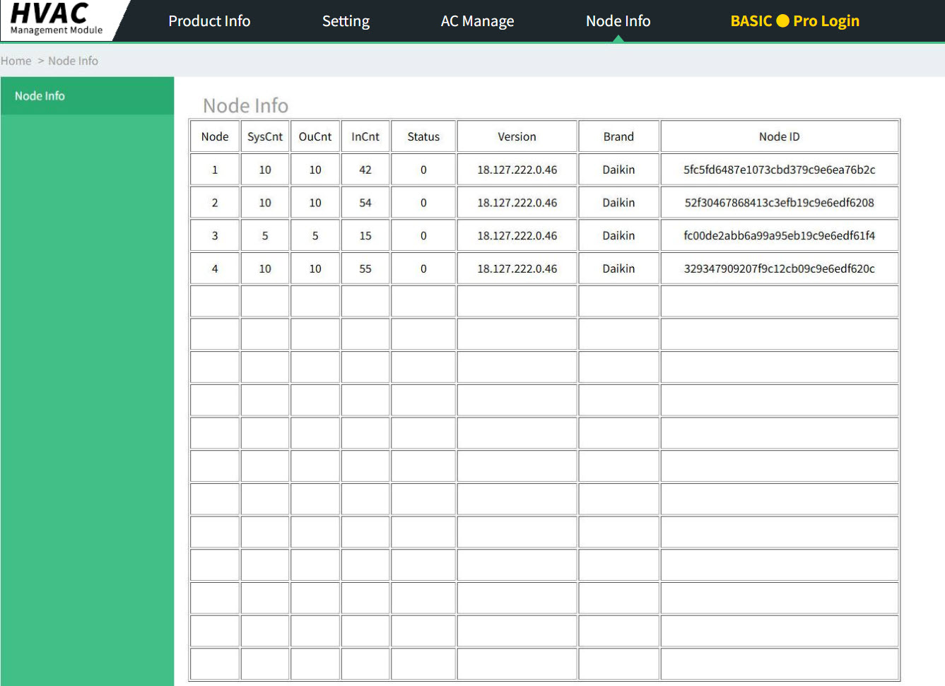
- Go to the Node Info interface to check if the brand under corresponding channel has been successfully changed.
- Restore power to the air conditioner’s outdoor unit.
- Wait for the device to automatically search for the indoor air conditioning
units
Step 6. Air Conditioner Management - Control the Air Conditioners
- Enter the AC Manage interface to view the air conditioners that have
been discovered.
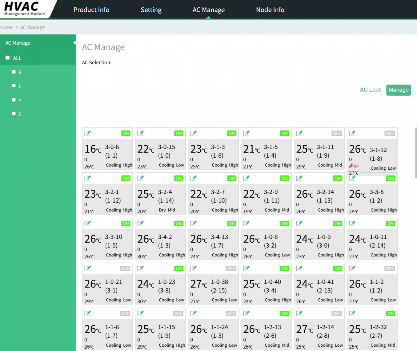
- Click on the corresponding air conditioner cards to select multiple units. Selected air conditioners will be displayed in the AC Selection bar at the top. You can also directly select all air conditioners under a single channel by using options 1, 2, 3, or 4 in the left-side AC Manage panel.
- Click Manage. In the new interface that appears, configure the
desired settings. After completing your selections, click
Submit.
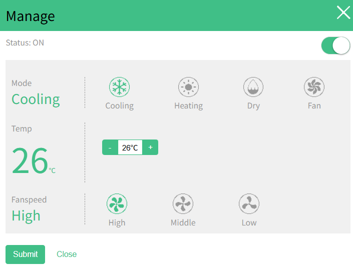
- After a control command is successfully sent, wait briefly for the air conditioner card information to sync and update.
Step 7. AC Location Record
- Physically change the temperature setting on an indoor unit on site, then look for which device in the management interface reflects the change, and make a note of the association between that the address of indoor unit and its physical location.
- Repeat the above steps until the spatial correspondence (mapping) of all air-conditioning units has been confirmed.
Appendix: VRF Compatibility & Wiring
Verify Brand Compatibility and Communication Terminals
Select the wiring terminals and connect the device according to the air conditioner brand, as shown in the table below.
| Brand | AC-Side Wiring Terminals | Outdoor Unit Connection Required |
|---|---|---|
| Daikin – Multiple Outdoor Units | F1, F2 (Outdoor–Outdoor) | Yes |
| Daikin – Single Outdoor Unit | F1, F2 (Indoor–Outdoor) | No |
| Mitsubishi Electric – Multiple Outdoor Units | M1, M2 (TB7) | Yes |
| Mitsubishi Electric – Single Outdoor Unit | M1, M2 (TB3) | No |
| Mitsubishi Electric – Lingyao | M1, M2 (Outdoor Unit); M1, M2 (Branch Box) |
No |
| Hitachi | 1, 2 | No |
| Toshiba | U1, U2 | No |
| Panasonic | U1, U2 | No |
| Hisense | 1, 2 | No |
| Haier | P, Q | No |
| YORK – Qingdao | 1, 2 | No |
| YORK – Guangzhou | A2, B2 or A, B | Yes |
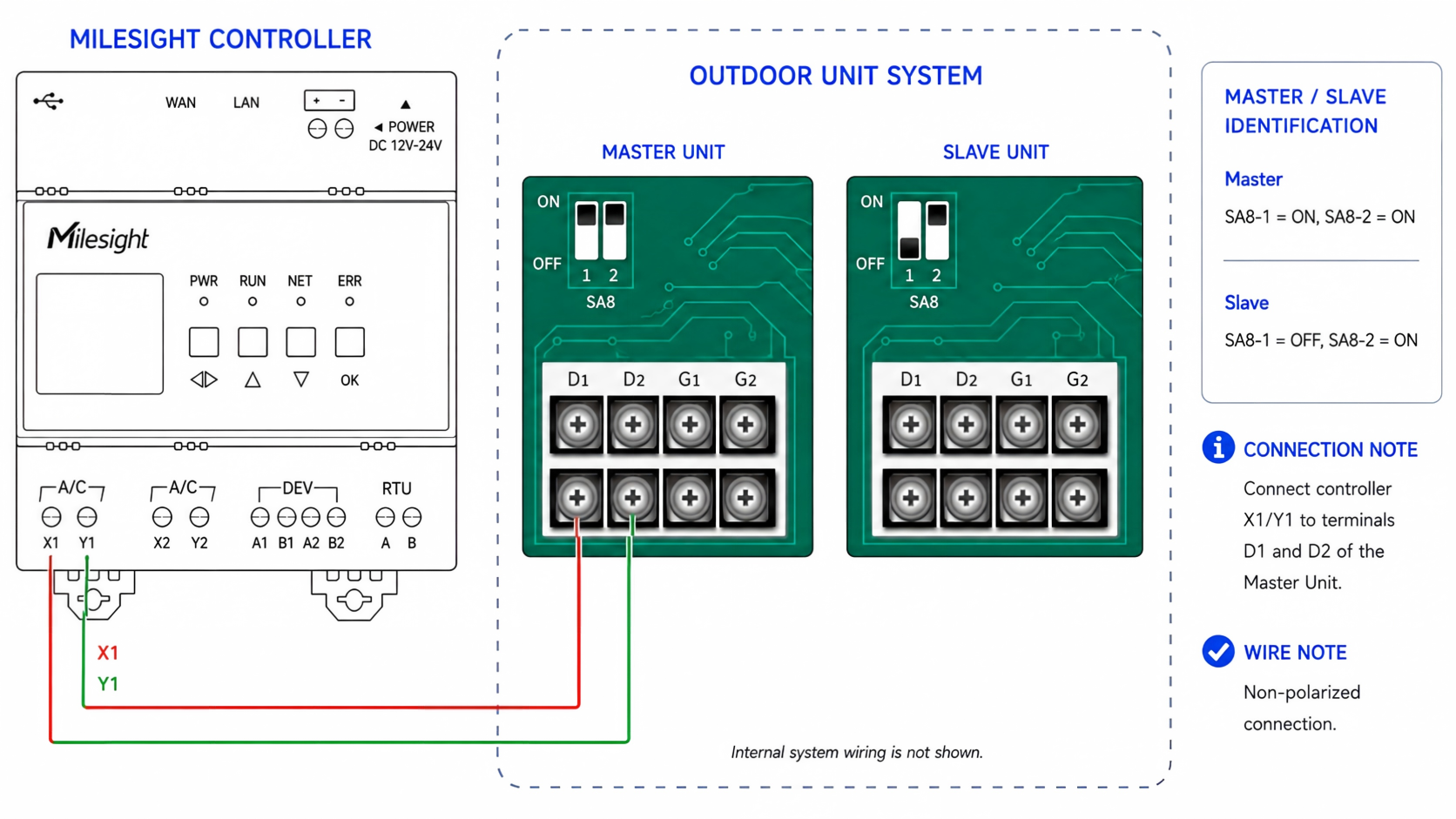
| Gree | G1, G2 | Yes |
| Gree | D1, D2 | No |
| TCL | F1, F2 | No |
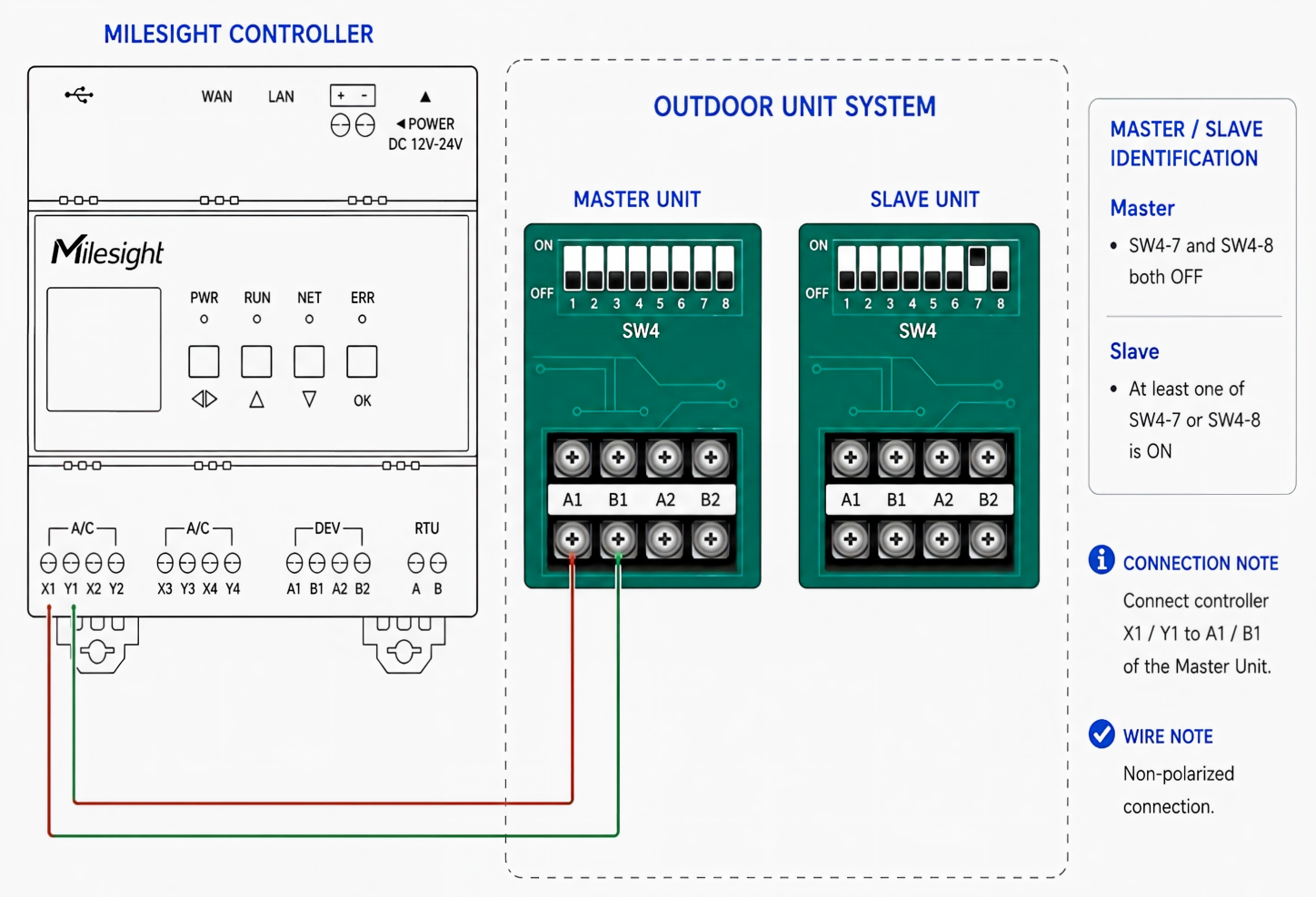
| Mitsubishi Heavy Industries | A1, B1 | No |
| Mitsubishi Heavy Industries | A2, B2 | No |
| Midea / Bosch / Carrier | X, Y | Yes |
| Midea / Bosch / Carrier | P, Q | No |
| Midea – Coolfree | A, B (Outdoor Unit) | Yes |
| AUX | A, B | No |
| Samsung | F1, F2 | No |
| LG | A, B (CEN) or IDU.AB, INT.AB | No |
| McQuay | Apc, Bpc | Yes |
| TICA | A1, B1 (commonly used) or A3, B3 | No |
| CHIGO | P, Q | No |
| Trane | A, B | Yes |
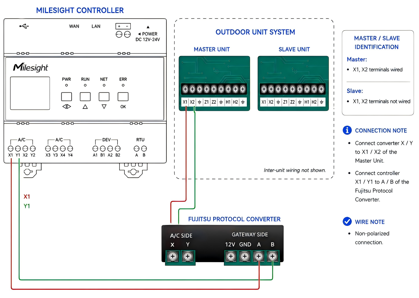
| Fujitsu | Protocol Adapter | Yes |
| Unsupported Brand | ||
| LENNOX | ||
Identify the Number of Outdoor Units
Each outdoor master unit is regarded as an independent air conditioning system and occupies one dedicated channel on the controller. The UC722 supports up to four channels, allowing it to manage up to four independent outdoor unit systems simultaneously.
This section describes several common methods to help identify the number of outdoor master units.
- Method 1: Roof Layout Drawings
-
- In the air conditioning system drawings, master and slave outdoor units are typically identified by the same model name, with their capacities expressed in the format xx + xx HP (for example, 10 HP + 10 HP).
- Count the independent refrigerant piping systems connected to the outdoor units. Each independent refrigerant pipe represents one outdoor master unit (one VRF system).
- Method 2: Building Layout Drawings
- You can also identify the number of outdoor master units by checking the vertical refrigerant pipe shafts (pipe risers) in the building layout drawings. Each independent refrigerant riser generally corresponds to one outdoor master unit.
Identify and Connect the Outdoor Unit
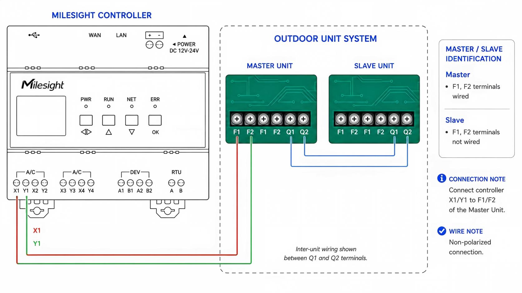
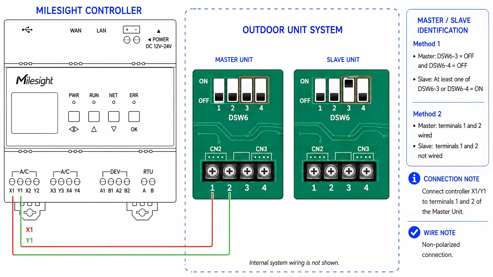
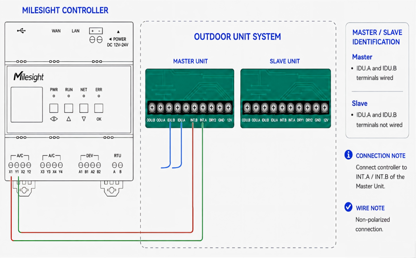
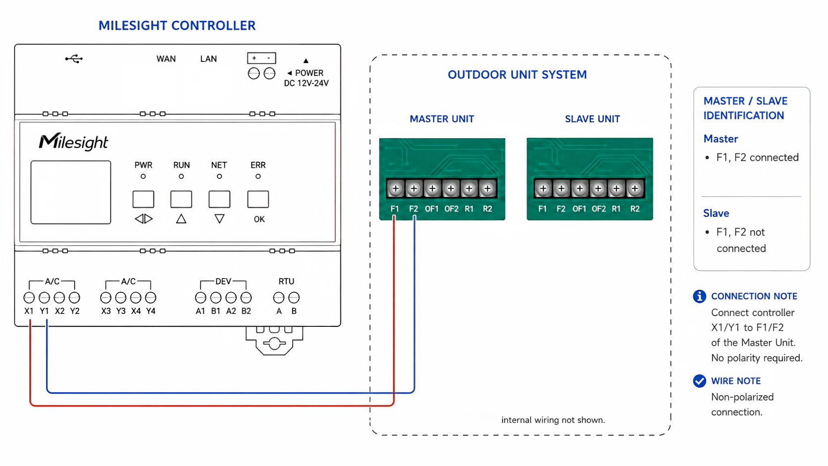
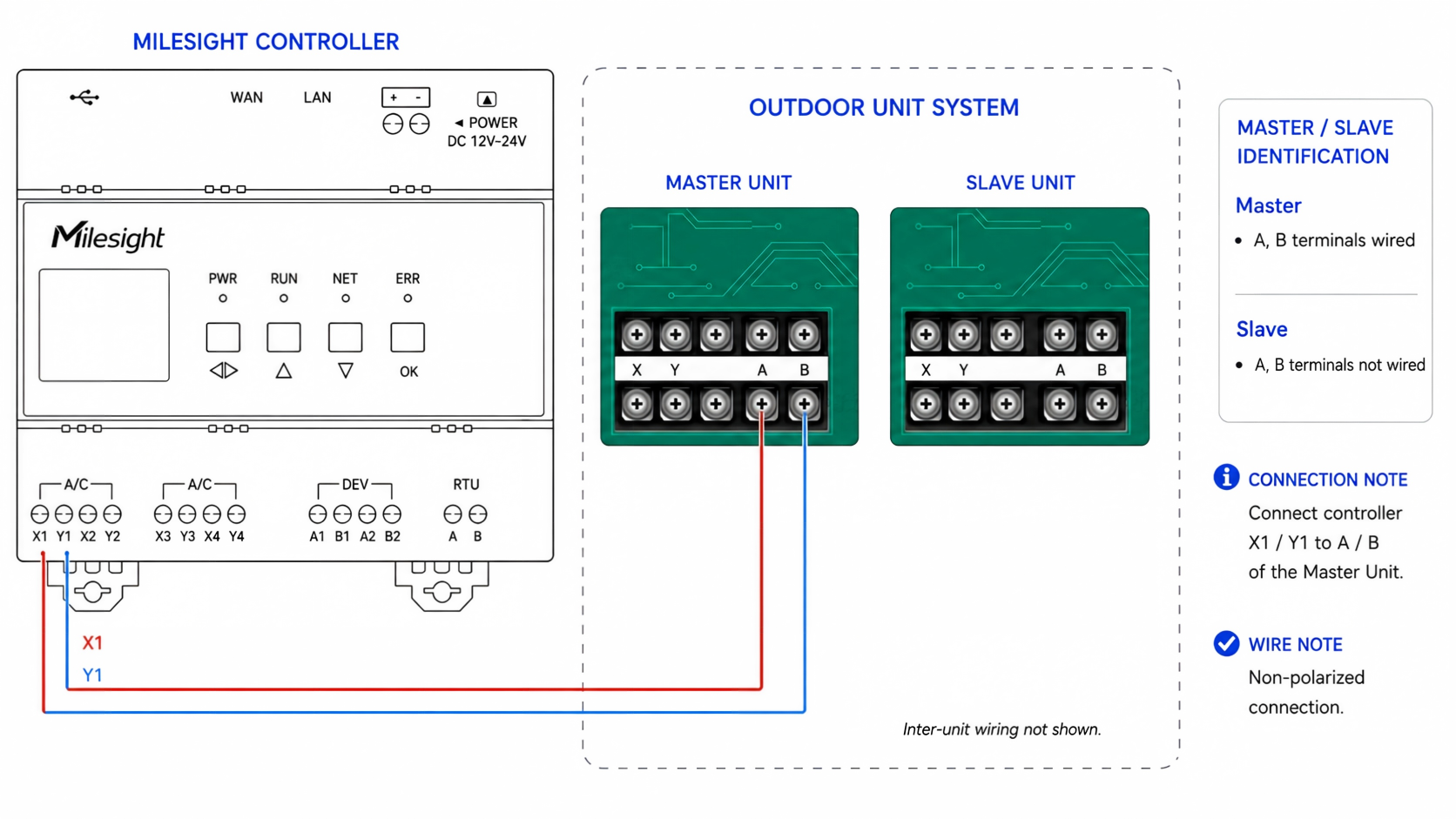
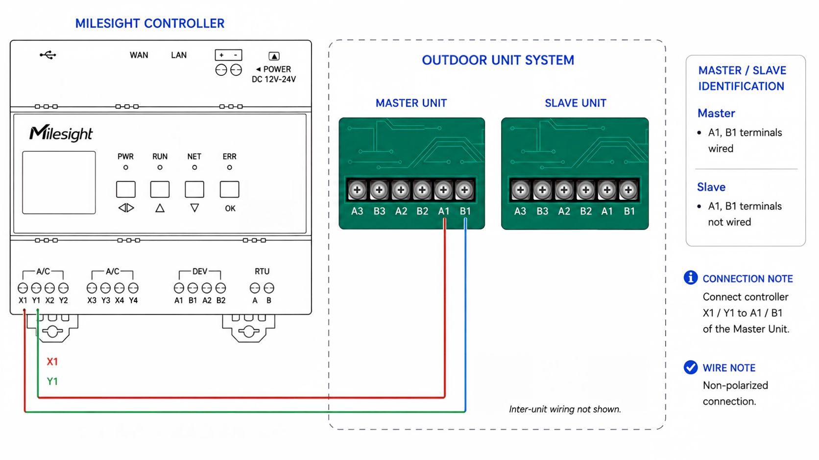
The communication terminals on the outdoor master unit are typically connected with communication wires, while slave units usually have no communication wiring connected. The following provides specific wiring diagrams.
- General Wiring Notes
-
- Controller fails to start → check power supply (DC 12 V / 2 A).
- Indoor unit polling: ~4 s/unit. Allow time for full discovery.
- Terminal resistor OFF for Daikin, Panasonic, Mitsubishi Electric (both options).
- Key Concepts Before Wiring
-
- Central controller: manufacturer's original centralized device, not the UC722.
- Protocol Converter: brand protocol → standard (e.g. Modbus).
- Single System: 1 line between indoor & outdoor (any unit count).
- Multi-System (Cascade): outdoor units cascade-linked.
- CHIGO
-
Note: Readable-but-not-controllable / H7 error → enable pull-up/down resistors.
-
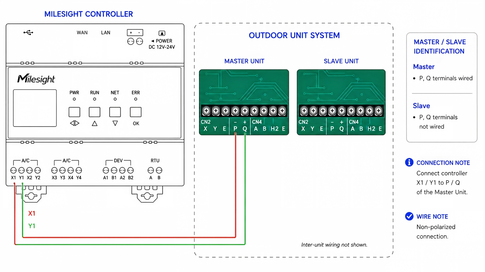
- DAIKIN
-
Note:
- Do NOT enable the terminal resistor.
- With central controller → set brand to "Daikin Central Controller"
-
- HITACHI
-
Note:
- With central controller → set brand to "Hisense" (more stable).
- Gen 3 central controller → "Hitachi-Master".
- The Hitachi A3 model is not supported, please contact the pre-sales team.
- TOSHIBA
-
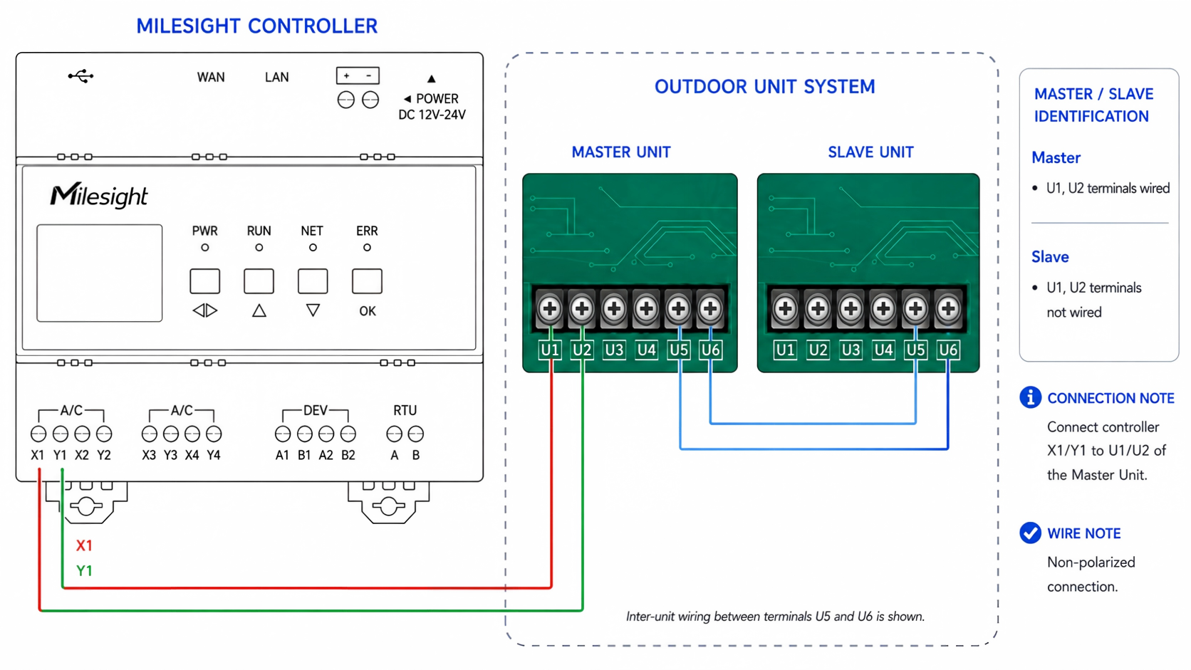
- MITSUBISHI_E
-
Note: Do NOT enable the terminal resistor.
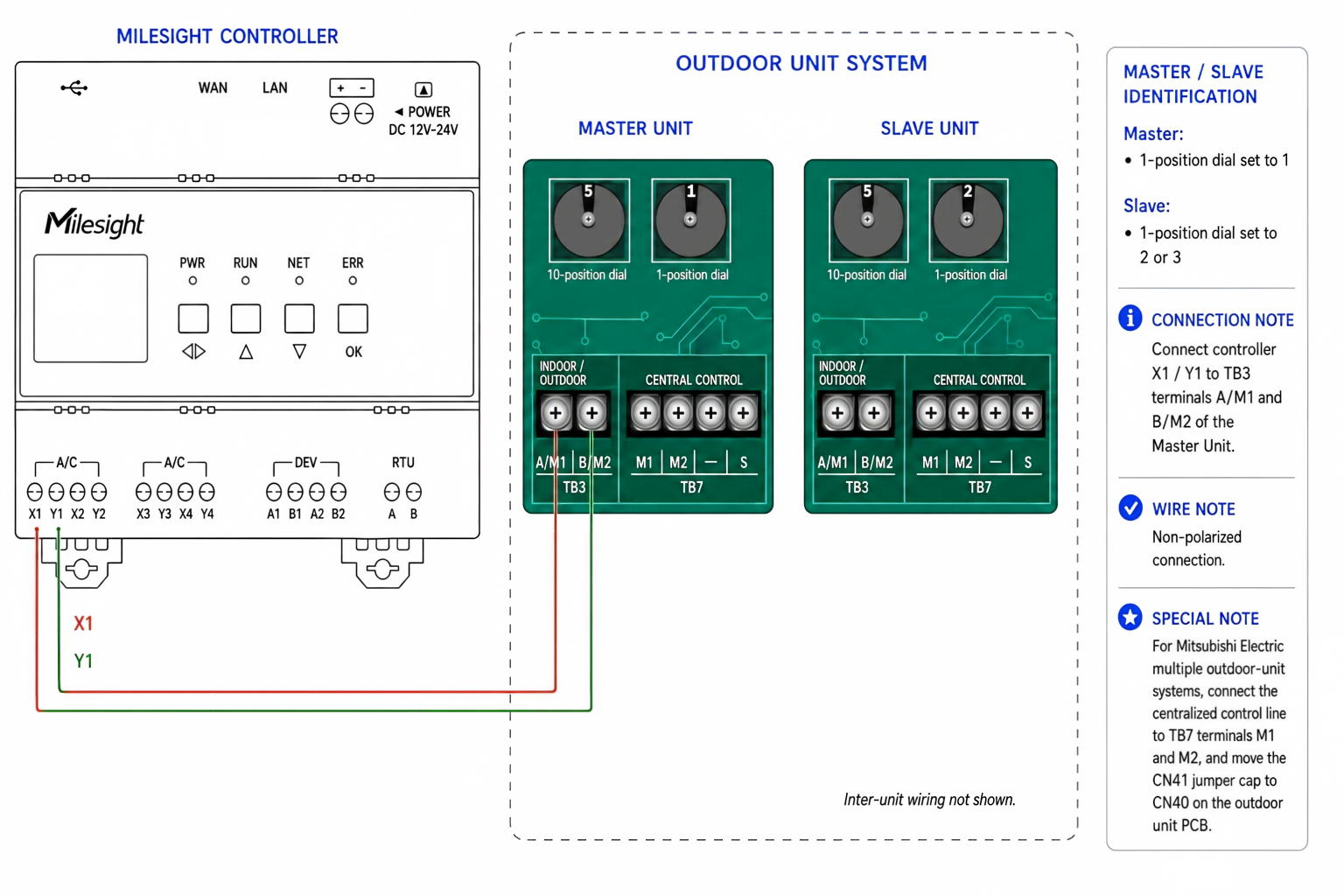
- MITSUBISHI_H
-
- GREE
-
Note:
- Gen 4: discoverable but not controllable → enable terminal resistor pull-up (or external 120 Ω if unstable).
- Gen 5: Please contact the pre-sales team when the controller cannot be remotely controlled.
- MIDEA
-
Note:
- Pre-V6: no dehumidification code on bus → displays as cooling.
- V8: connect to XY terminals, set brand to "Midea XY".
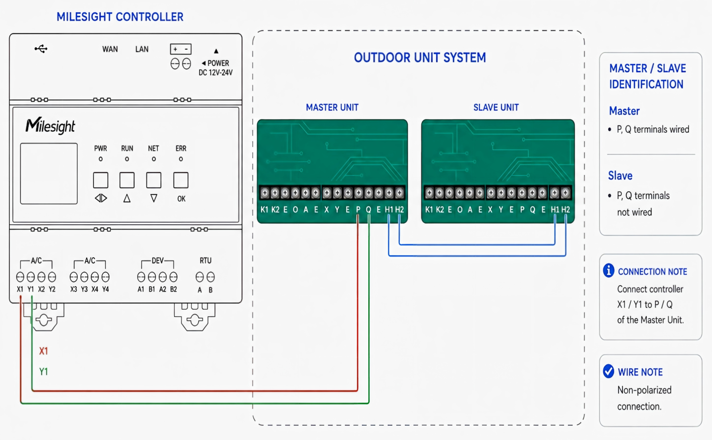
- HAIER
-
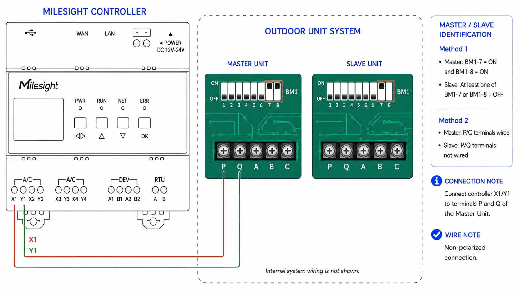
- HISENSE
-
Note:
- The M3 model is not supported, please contact the pre-sales team.
- Error A6 → check if both master & slave outdoor units have communication wires connected.
- LG
-
- SAMSUNG
-
- PANASONIC
-
Note: Do NOT enable the terminal resistor.
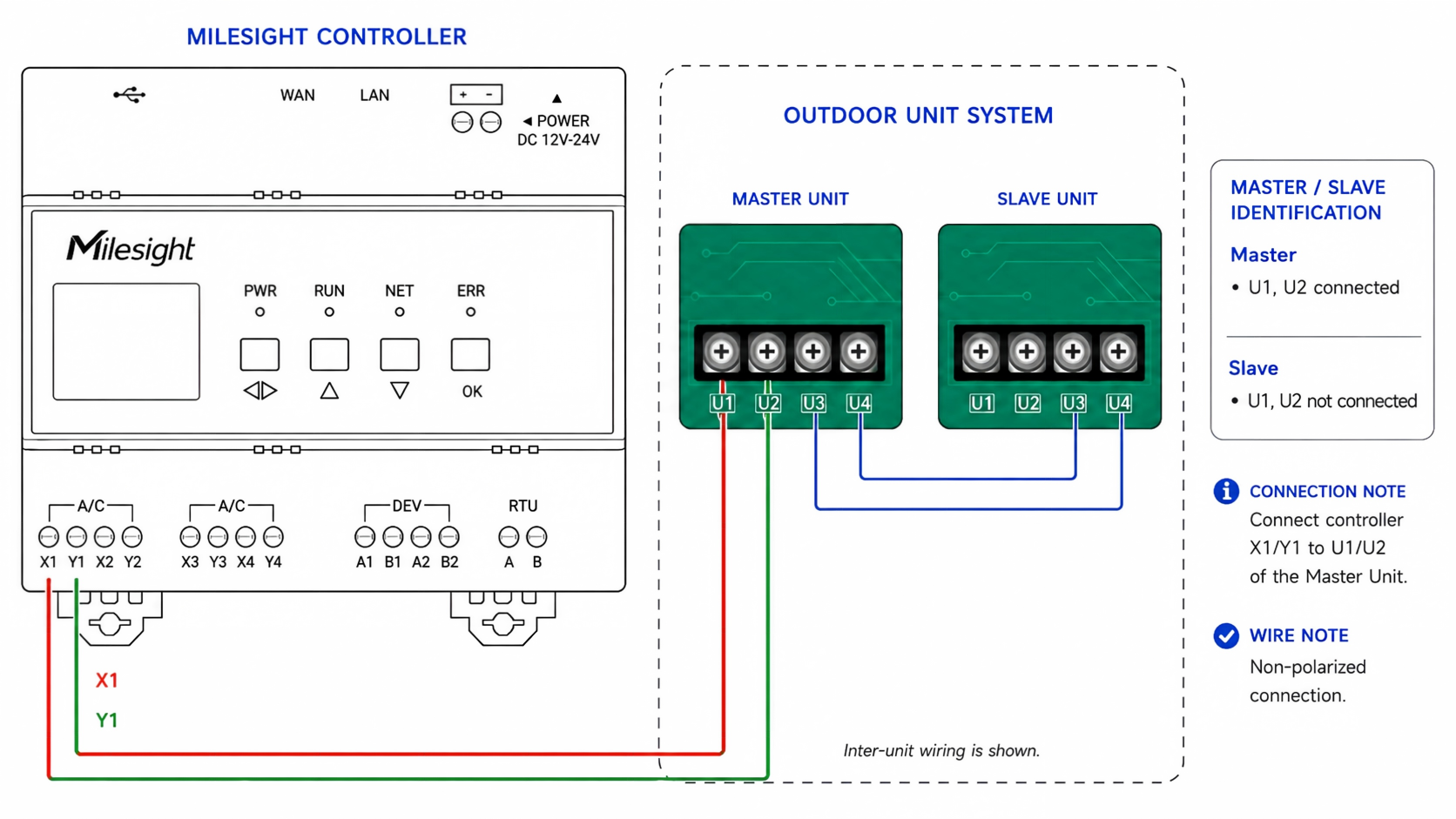
- YORK (QD)
-
Note: The Gen 3 model is not supported, please contact the pre-sales team.
- YORK (GZ)
-
Note: For some older models, one channel can connect up to 16 indoor units at most. If the number exceeds this limit, a second channel is required.
- FUJITSU
-
- TICA
-
Note: A1/B1 and A3/B3 supported. A3/B3: single-system only (no cascade).
- MCQUAY
-
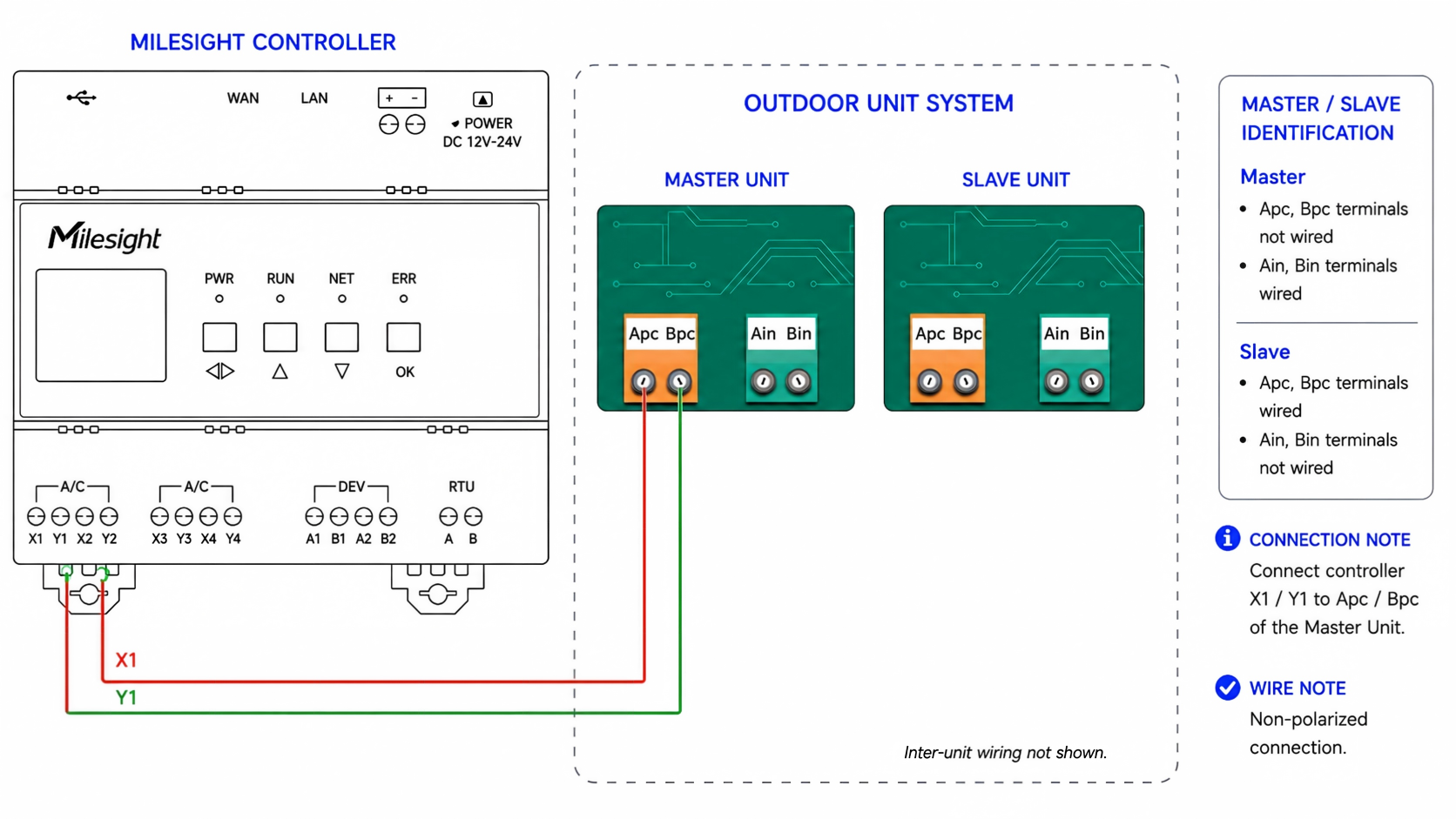
- CARRIER
-