Quick Start Guide
Packing List
 |
 |
 |
| 1 × VS373 Device | 1 × Type-C Power Adapter | 4 × Ceiling Mounting Kits |
 |
 |
 |
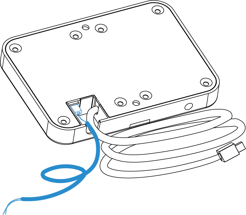
| 2 × Spring Clips | 2 × Silicone Plugs | 1 × DO Wiring |
 |
 |
 |
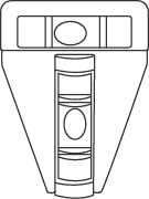
| 1 × T-shaped Spirit Level | 1 × Warranty Card | 1 × Installation Guide |
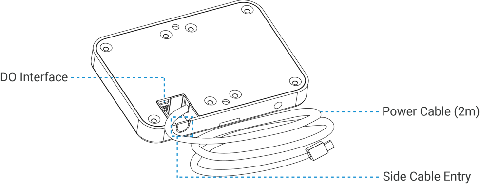
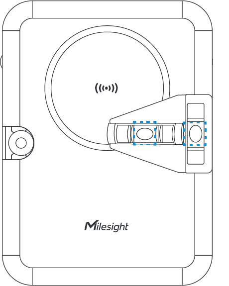
Hardware Overview
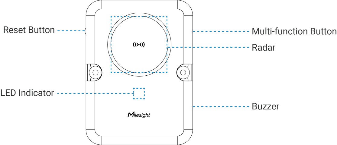
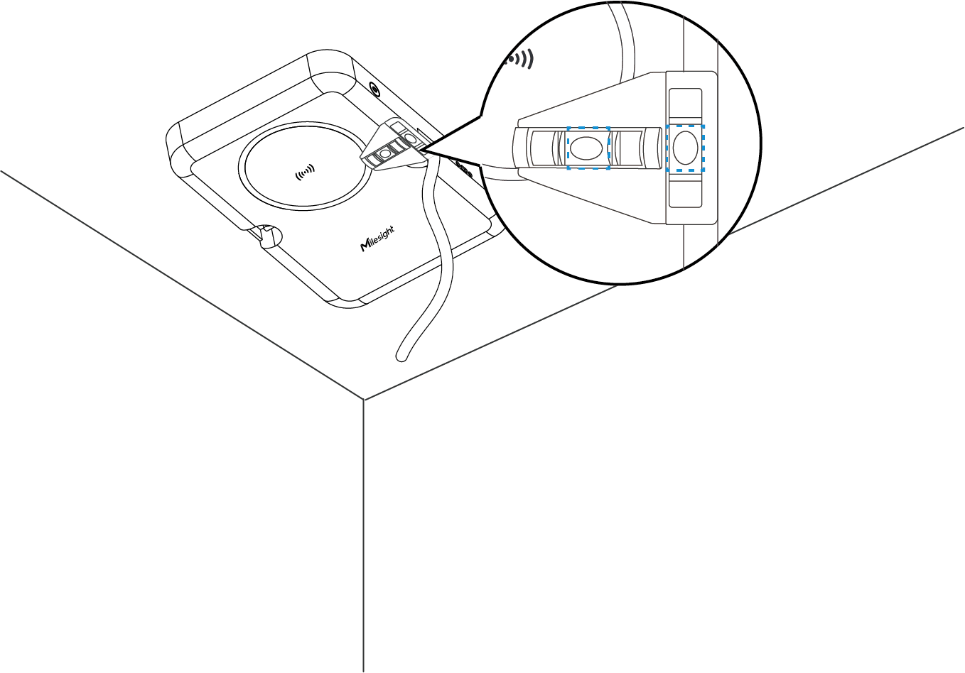
Button and LED Descriptions
| Function | Action & Description | LED Indication |
|---|---|---|
| Turn On/Off Wi-Fi | Press and hold the Multi-function button for 2~5 seconds | Wi-Fi On: Green Light on |
| Wi-Fi Off: Green Light Blinks Slowly | ||
| Enable Wi-Fi STA Mode | Press and hold the Multi-function button for 2~5 seconds | Blue Light on |
| Turn On Radar | Radar Initializing | Green Light Blinks Quickly |
| Reset to Factory Default | Press and hold the reset button for 10 seconds | Blue Light Blinks Quickly |
| Fall Alarm | Fall event occurred | Red Light Blinks Quickly |
| Stop Alarm | Press and hold the reset button for 6~9 seconds | Green Light Stays On or Blinks Slowly |
| Device Abnormality | Radar anomaly; WiFi anomaly | Red Light Stays On |
Power Supply
-
Powered by Type-C Power Adapter (5V, 3A)

Where:
R—Cable Resistance in Ω, refer to Wire Resistance Calculator.
Installation Location
Installation Height: 2.3~3m.
Installation Location: Ensure the center of radar placed in the center of detection area. Take a room without any objects as example, place the device on the ceiling with the center of radar matching the center of the room. The long side of the device should align with the longer dimension of the room, while the short side should align with the shorter dimension of the room.

- If the centered position of the room ceiling is not suitable for mounting the device, find a proper position that is at least 1 meter away from the wall.
- Ensure the installation location of the device is flat and stable to avoid tilting or instability.
- Avoid installing the device near ceiling fans or chandeliers.
- Minimize the accumulation of cabinets or clutter within the device's detection range, and avoid the presence of large metal surfaces, mirrors, or other reflective objects nearby.
- The room size, installation height, and detection height should be accurately measured using tools such as a rangefinder or tape measure before setting.
Installation Steps
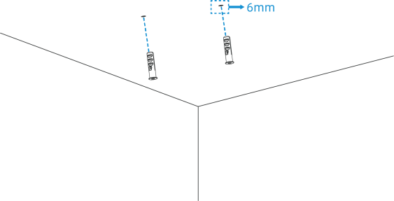
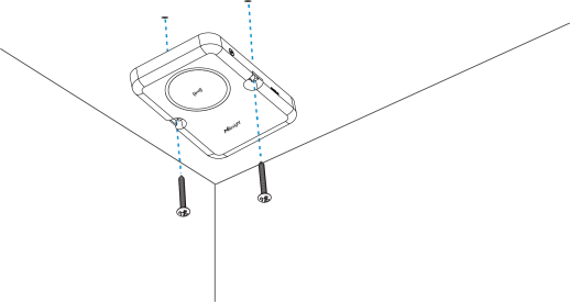
Ceiling Mount

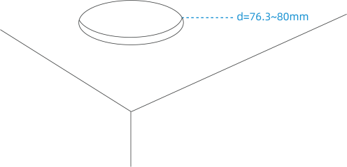
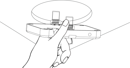
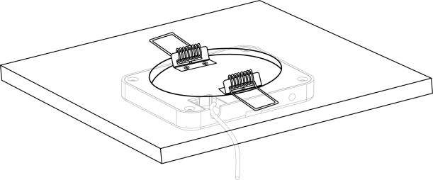
Cutout Mount


Access the Web GUI
VS373 provides user-friendly web GUI for configuration access via Wi-Fi. Users need to customize the password when using the device for the first time. The default settings are as below:
Wi-Fi SSID: Fall Detection_XXXXXX (can be found on the device label)
Wi-Fi IP: 192.168.1.1
Enable the Wireless Network Connection on your computer, search for corresponding Wi-Fi SSID to connect it, then type 192.168.1.1 to access the web GUI.
FCC Statement
Any changes or modifications not expressly approved by the party responsible for compliance could void the user's authority to operate the equipment. This device complies with part 15 of the FCC Rules. Operation is subject to the following two conditions:
- This device may not cause harmful interference, and.
- This device must accept any interference received, including interference that may cause undesired operation.
-Reorient or relocate the receiving antenna.
-Increase the separation between the equipment and receiver.
-Connect the equipment into an outlet on a circuit different from that to which the receiver is connected.
-Consult the dealer or an experienced radio/TV technician for help.
FCC Radiation Exposure Statement:
This equipment complies with FC radiation exposure limits set forth for an uncontrolled environment. This equipment should be installed and operated with minimum distance 20cm between the radiator& your body. This transmitter must not be co-located or operating in conjunction with any other antenna or transmitter.