Install the Device
Limitation
The thermostat is designed for 24VAC systems only. Do not install it on high-voltage, high-current, or millivolt systems!
Prerequisites
- Ensure the thermostat is compatible with the target HVAC system.
- Ensure the wire diameter complies with the AWG 24-18 standard.
- Ensure there is a C wire or common wire. If no C wire, it may need a C-Wire Power Extender Kit.
- Check the default accessories in the box.
- Prepare the following additional tools: Screwdriver, Pencil, Drill (15/64" or 1/4" drill bits), Crimping pliers (for WT211)
Installation Location
The thermostat supports receiving ambient temperature and humidity data from either internal sensors or external servers/devices. It is important to choose appropriate installation locations to collect accurate environmental data and ensure precise control.
It is recommended to install the thermostat about 4-5 ft. (1.2-1.5m) above the floor,
in an area with good air circulation at average temperature. If installation in an
optimal location is not feasible, consider using external data sources.
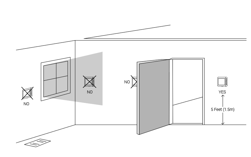
Do not install the device where:
- Close to hot or cold sources like hot or cold air ducts;
- The place in direct sunlight;
- Dead spots or drafts (behind the doors and in corners);
- In areas that do not require conditioning;
- Close to concealed chimneys or pipes;
- Close to metal objects and large obstacles which affect the wireless transmission;
- The place with lots of electromagnetic interference;
- The place where strong vibration may happen or easy to be subjected to physical shock.
Installation Steps
Step 1. Remove the Old Thermostat
- Power off the HVAC system by using the master switch or circuit breaker.
- To confirm power is off, adjust the temperature on the
current thermostat and wait for a few minutes. If the system does not respond
accordingly, the power is shut off successfully.Warning: Failure to follow these steps may result in personal injury and/or death from electric shock.
- Remove the current thermostat cover from the wall.
- Take a photo of the wires connected to the terminals of the old thermostat for
reference.CAUTION: If you see the system is labeled with wires L1 and L2, or any high-voltage indicators like 110V, 120V, or 240V, it means the thermostat is not compatible with this system. DO NOT CONTINUE INSTALLATION.
- Disconnect the wires from old thermostat and label the wires with
stickers.
- Unscrew the backplate of the old thermostat and remove it from the wall. Be careful not to let the wires fall into the wall holes.
Step 2. Install the Backplate of the New Thermostat
- (Optional) Press the wiring backplate onto the decorative cover plate to fix
them together. If you do not use the decorative cover plate, skip this
step.Tip: It is recommended to use the decorative cover plate to cover the holes on the wall left by the old thermostat, and to reduce the airflow from the holes that affect the ambient temperature measurement of the new thermostat.
- Position the wiring backplate against the wall to check if the wall anchors from the old thermostat align with the screw holes of the backplate.
- If the backplate does not align with existing anchor holes, mark the new screw
hole locations with a pencil. Then drill the two mounting holes.Tip: Use a level to ensure the thermostat is properly aligned before marking the screw hole locations.
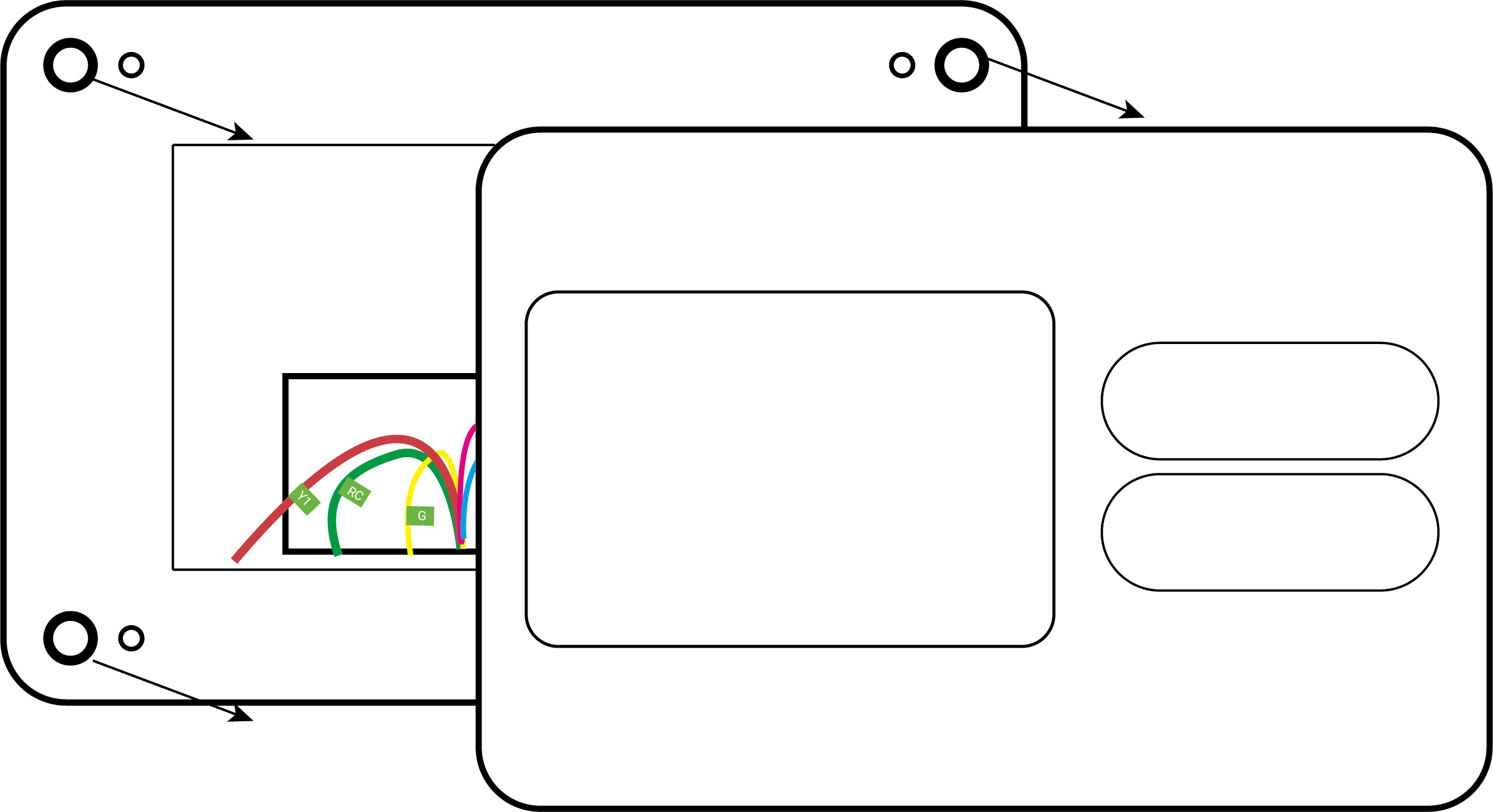
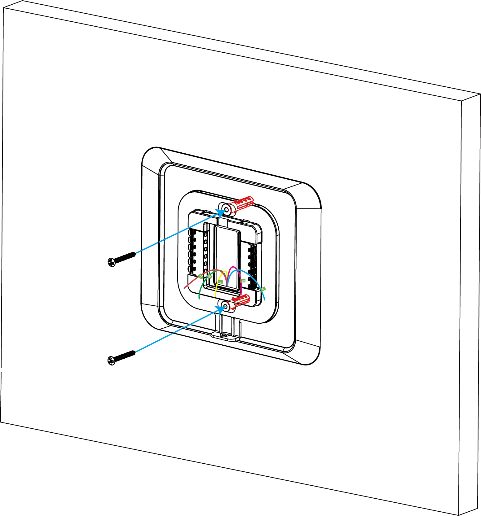
- Pass the wires through the middle opening in the backplate, then secure the
backplate (with decorative cover plate) to the wall using the wall plugs and
mounting screws.
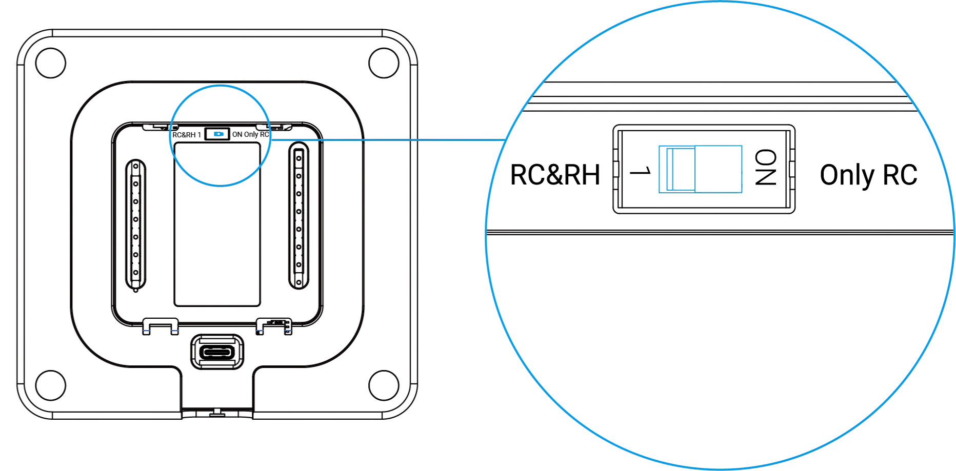
Step 3. Adjust Power Jumper for New Thermostat
- WT201
-
- Confirm your HVAC system type and wirings.
- If you use a two-transformer HVAC system which has two independent
power wires (like RC and RH), adjust the DIP switch of the
thermostat to RC&RH; if you use a single-transformer HVAC
system which has only one power wire (like R or RC), adjust the DIP
switch to Only RC.CAUTION: Ensure the DIP switch positions match the HVAC system; otherwise, it may cause the thermostat to malfunction or even become damaged.
- WT211
-
- Confirm your HVAC system type and the wirings.
- By default, there is a jumper between the terminal RC and RH. Follow the
instructions according to your HVAC system:
System Type Step Two-transformer HVAC system with two independent power wires (like RC and RH) - Hold the tabs of the terminal blocks to unplug the jumper.
Single-transformer HVAC system with only one power wire (like R or RC) - Make sure that there is a length of insulation stripped from the jumper and the power wire.
- Twist the jumper and the power wire together and cover them with the wire crimp cap.
- Crimp the wire crimp cap with crimping pliers.
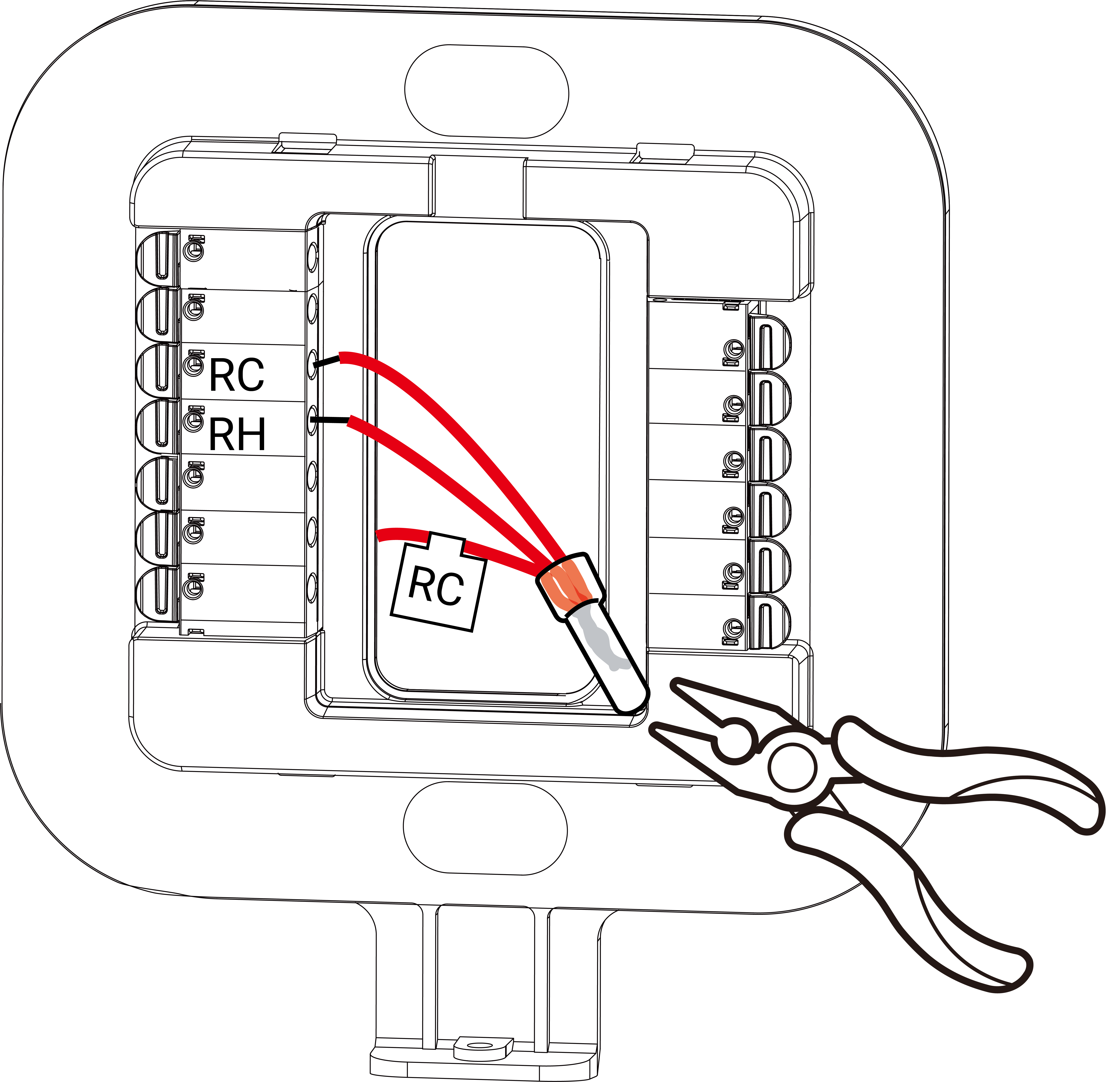
CAUTION: Ensure the jumper status matches the HVAC system; otherwise, it may cause the thermostat to malfunction or even become damaged.
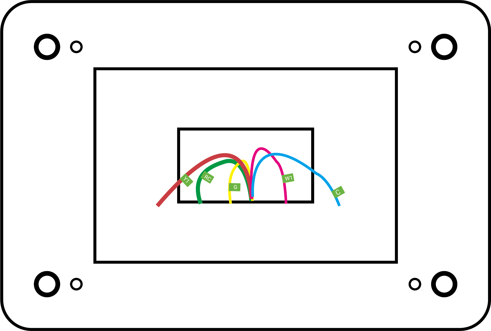
Step 4. Wire the New Thermostat
- Make sure that about 6.5 mm of insulation is stripped from the end of the used wires.
- According to the wiring diagram, hold
the tabs and insert the wires into the side holes of the corresponding terminals
on the wiring backplate until they are firmly in place. If you need to release
the wires, press the terminal tabs again and pull out the wires.
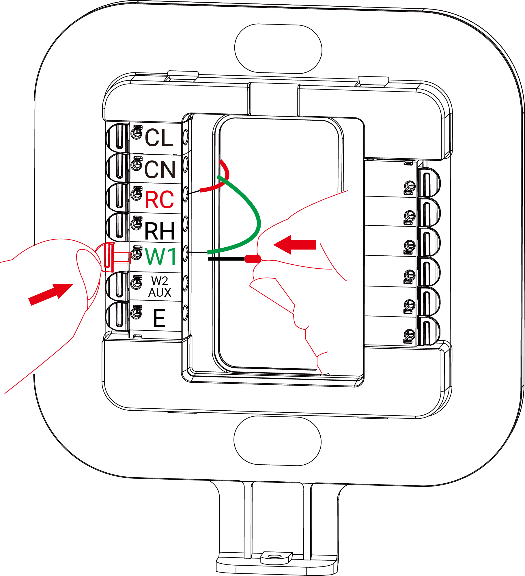
- Gently tug the wires to ensure that they are securely connected.
- Push the excess wires back into the hole on the wall and ensure no drafts are coming from it.
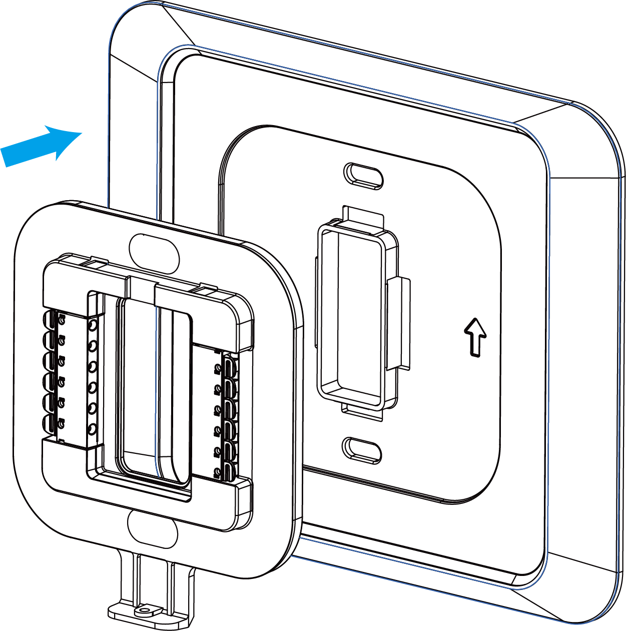
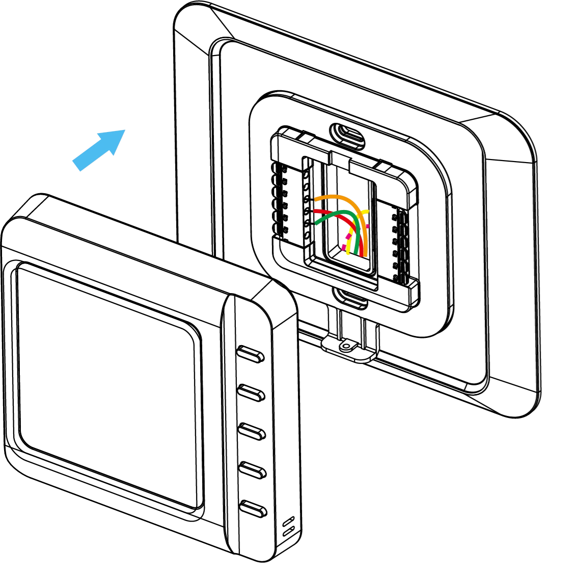
Step 5. Install the New Thermostat
- Align the thermostat to the wiring backplate and push it until it clicks into
place.
- Power on the HVAC system by using the master switch or circuit breaker. After
powering on, check the device as follows:
- Whether the screen displays the temperature and humidity data.
- Press the top button (Button 1) to check whether the HVAC system can be turned on or off.
- Press buttons to switch temperature control mode and fan mode to check if the HVAC system responds correctly.
- Check whether the network icon on the screen is static on to determine if the thermostat has joined the network.
- (Optional) Whether the keycard switch works.
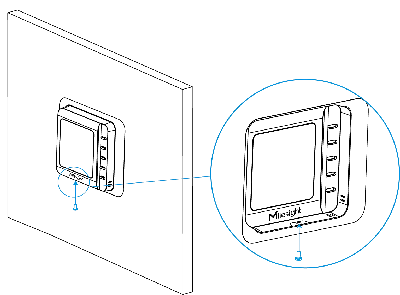
- Fix the bottom of the thermostat to the wiring backplate with a fixing
screw.