6.1.1 Operations on Live View Page
[Display Control]
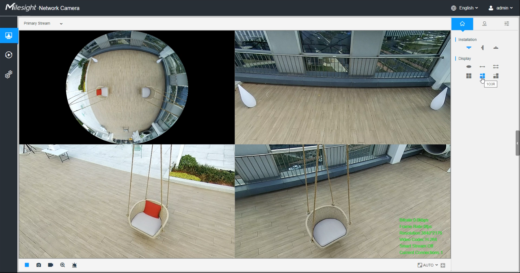
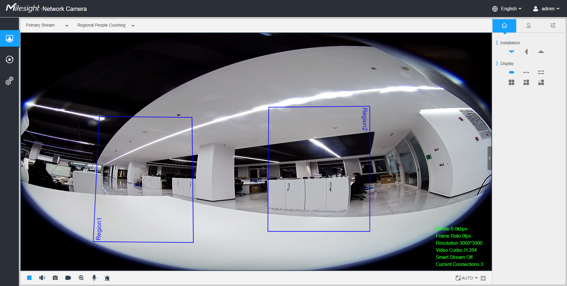
Display Control allows you to select install type, display mode, window screen and channel of live view.
| Item | Parameter | Description |
|---|---|---|
| Dewarping Rule |
|
Click to select on-board dewarping mode. |
|
Client-side Dewarping |
Click to select client-side dewarping mode. | |
| Installation |
|
Click to select ceiling mounting. |
|
Click to select wall mounting. | |
|
Click to select flat mounting. | |
| Display |
|
Select live view of original fisheye view. |
|
Select live view of 360° panoramic view. | |
|
Select live view of two 180° panoramic views. | |
|
Select live view of four regional views. | |
|
Select live view of one original fisheye view and three regional views. | |
(Only for Hardware Dewarping) |
Select live view of one 360° panoramic view and three regional views. | |
(Only for Multi-Channel Mode of Hardware Dewarping) |
Select live view of one original fisheye view, one 360° panoramic view and three regional views. | |
(Only for Software Dewarping) |
Select live view of one 360° panoramic view and one regional view. | |
(Only for Software Dewarping) |
Select live view of one 360° panoramic view and four regional views. | |
(Only for Software Dewarping) |
Select live view of one 360° panoramic view and six regional views. | |
(Only for Software Dewarping) |
Select live view of one original fisheye view and eight regional views. | |
| Channel | (Only for Multi-Channel Mode) |
Click to play this channel on any window of live view. |
| Window | Window Layout (Only for Multi-Channel Mode) |
Click to set window layout to “1*1”/ “2*2”/ “1+4”. |
Window Size |
Click to display images at a window size. | |
Real Size |
Click to display images at a real size. | |
Full Screen |
Click to display images at full-screen. |
- Original fisheye view: the whole wide-angle view of the fisheye camera is displayed.
- Panoramic view: the round fisheye image is transformed to rectangular image by certain calibration methods.
- Regional view: the close-up view of defined area in the original fisheye view or panoramic view.
- Select the Installation, Display mode and the most appropriate Window Layout in sequence.
[Live View Window]
| No. | Parameter | Description |
|---|---|---|
| 1 | Live Video |
Click to access the live view page. |
| 2 | Playback |
Click to access the playback page. |
| 3 |
|
Click to access the configuration page. |
| 4 | Click to select system language. | |
| 5 | Display the user name and click to logout. | |
| 6 | Choose the stream (Primary/Secondary/Tertiary) to show on the current video window. | |
| 7 | Choose the options (Hide
Detection Region/Region Entrance/Region Exiting/Advanced
Motion/Line Crossing/Loitering/People Counting/Object
Left/Object Remove/Regional People Counting) to hide/display
detection region on the current video window.
|
|
| 8 |
|
When recording, the icon appears. |
| 9 | Alarm |
When an alarm of VCA event was triggered, the icon appears. |
| 10 | Alarm |
When an alarm of people counting was triggered, the icon appears. |
| 11 |
Alarm |
When an alarm of Motion Detection was triggered, the icon appears. |
| 12 | Alarm |
Except for the three kinds of alarms above, when other alarms were triggered, the icon appears. |
| 13 |
Stop/Play |
Stop/Play live view. |
| 14 | Snapshot |
Click to capture the current image and save to the configured path. The default path is: C:VMS\+-1\ IMAGE-MANUAL. |
| 15 |
Start/Stop Recording |
Click to Start Recording video and save to the configured path. The default path is C:VMS\+-1\MS_Record. Click again to Stop Recording. |
| 16 |
Digital Zoom |
When enabled, you can zoom in a specific area of video image with your mouse wheel. |
| 17 |
Manual Output |
Manually trigger Camera Alarm Output. |
| Brightness: Adjust the Brightness of the scene. | ||
| Contrast: Adjust the color and light contrast. | ||
| Saturation: Adjust the Saturation of the image. Higher Saturation makes colors appear more "pure" while lower one appears more “wash-out”. | ||
| Sharpness: Adjust the Sharpness of image. Higher Sharpness sharps the pixel boundary and makes the image looks “more clear”. | ||
| 2D DNR/3D DNR: Adjust the noise reduction level. | ||
| Default: Restore brightness, contrast and saturation to default settings. |
[PTZ Control]
PTZ Control allows you to use pan/tilt/zoom/preset/patrol function of PTZ, and set PTZ speed.
| No. | Parameter | Description |
|---|---|---|
|
PTZ Control |
Navigation key is used to control the direction. The rotation key is used for auto-rotation. | |
|
PTZ Speed |
To adjust the speed of pan/tilt movements, from 1 to 10 . | |
Zoom-/Zoom+ |
Click to zoom in and zoom out. | |
| Auto Tracking: With this option
enabled, the camera can perform the digital Pan/Tilt/Zoom to track the
moving objects automatically. Note:
|
||
| Enable to set the preset positions for each regional view channel. | ||
| Enable to set the patrol paths for each regional view channel. |