Compatibility
This chapter introduces the device compatibility and describes the steps to check the compatible systems.
Compatible HVAC Systems
The controller is compatible with the following systems:
- PTAC (Up to 1-cool/2-heat)
- Heat Pump System (Up to 1-cool/1-heat)
- Heat Pump System with AUX Heat
- Conventional HVAC System (Furnace + Air Conditioner, up to 1-cool/1-heat)
How to Check HVAC System Compatibility
- Power off the HVAC system by using the master switch or circuit breaker.
- To confirm power is off, adjust the temperature on the
current thermostat and wait for a few minutes. If the system does not respond
accordingly, the power is shut off successfully.Warning: Failure to follow these steps may result in personal injury and/or death from electric shock.
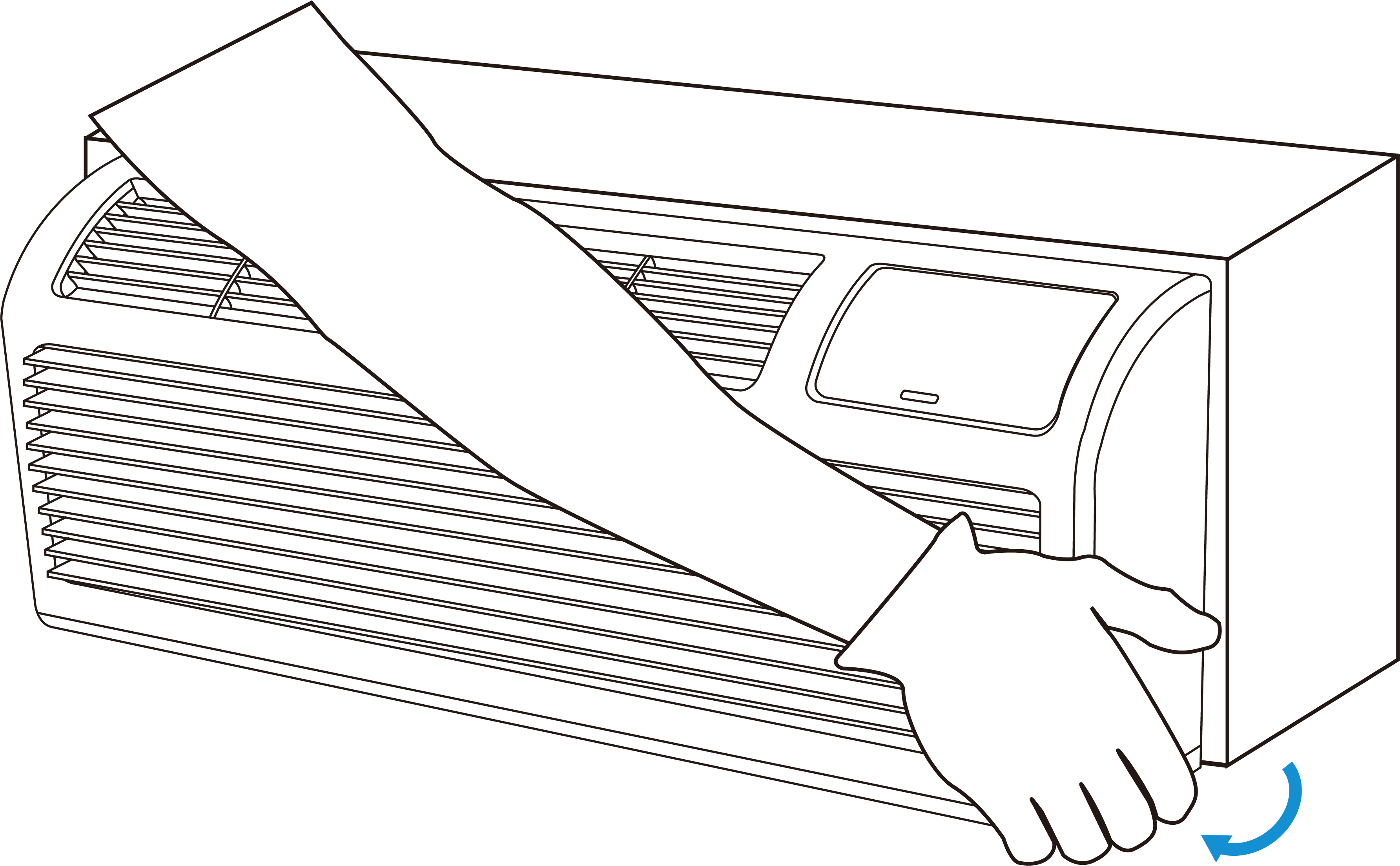
- Remove the cover of the HVAC system.
- Check whether HVAC system can supply the controller with 24 VAC and that the current supplied to the controller does not exceed 1A. If the system is labeled with L1 and L2, or with high-voltage indicators such as 110V, 120V, or 240V, the controller is not compatible with the system. Otherwise, continue to the next step.
- Identify the wires in use by checking the labels on the previous thermostat or the HVAC control terminals.
- Compare the existing wire labels with the following table, wiring
diagrams or use Compatibility Checker to determine the
system compatibility.
HVAC Wire Label (s) Description C Common wire of 24 VAC power. If there is no C wire, check if this wire is labelled as other names (like B). R/RH/RC Power wire. If there is only one R/RC/RH wire, it may provide both heating and cooling system power. If both RH and RC are present, contact a local professional installer or Milesight to confirm compatibility. Y/Y1 In conventional systems, Y/Y1 controls the 1-stage cooling. In heat-pump systems, Y1/Y1 controls the 1-stage compressor for cooling/heating. W/W1 In conventional systems, W/W1 controls the 1-stage heating. In heat-pump systems with auxiliary heat, W/W1 controls the 1-stage auxiliary heat. G/G1 Controls the fan. For a single G wire, connect this wire to GL of the controller. GL/G1 Low-speed fan control. GM/G2 Medium-speed fan control. GH/G3 High-speed fan control. O/B In heat pumps, O/B controls the reversing valve to switch between heating and cooling. If there is only one O wire or B wire, connect this wire to O/B of the controller. - If a wire label is not listed above, or if compatibility is difficult to determine, take a clear photo of the terminals and send it to local professional installer or Milesight.
NTC/DI Input Compatibility (Under Development)
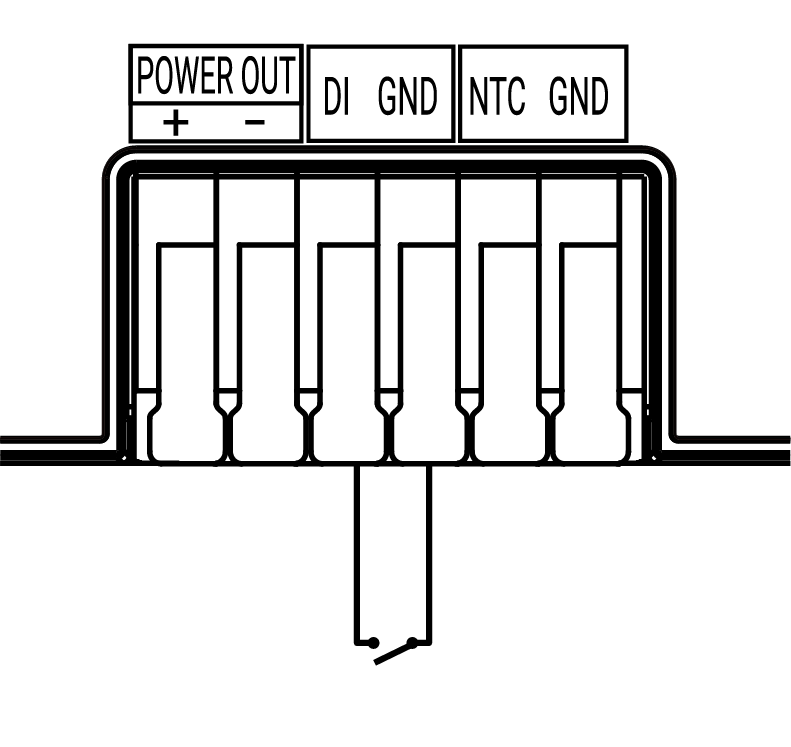
The controller is equipped with NTC and DI interfaces for connecting external
sensors. Before installation, check the requirements below to determine whether the
external sensor can be connected to the controller.
| Interface | External Device Type | Requirement |
|---|---|---|
| Digital Input | Key card, magnetic switch, or other physical switch | The device must provide a passive, voltage-free dry contact. |
| NTC | NTC temperature sensor | It is recommended to use the NTC sensor provided by Milesight to ensure compatibility and reliable performance. |
CAUTION: The DI input is a dry contact
input. Do not connect powered (active) signals to the dry contact input. Doing
so may damage the device.