Hardware Installation
This chapter describes the preparation and installation procedures for mounting the gateway and its accessories at the deployment site.
Tip: It is suggested to install the gateway on a sunny day for
solar panel adjustment and charging.
Prerequisites
- Check the Accessories
-
The gateway with the solar panel can be mounted on a wall or a pole. Select the required mounting method and prepare the corresponding mounting accessories.
- Check the SIM Card
- Make sure the Nano (4FF) SIM card is installed and the SIM cover is tightened to prevent water from entering the gateway. The specified tightening torque is 0.7 N.m. See Insert the SIM Card.
- Check the Battery Pack
- Make sure the battery pack is installed in the battery compartment and the compartment cover is secured with the fixing screw. See Install the Battery Pack.
- Check the Power Supply
- The gateway can be powered by a 12-24 VDC external power supply or the solar panel. The internal battery pack is charged when an external power source is available and can power the gateway when the external supply is disconnected or solar power is insufficient.
Select Installation Location
- The antennas must extend beyond the wall or pillar surface and not be close to the poles or walls. If there are still walls nearby, please keep the antennas at least 35cm away from them.
- Ensure there are no obstacles or metal objects around.
- For better coverage, it is recommended to position the gateway at a higher location, but not the highest position.
- The wall or pole structure shall be sufficiently solid and stable to ensure overall mounting stability.
- Screw mounting positions must avoid internal wall electrical wiring, water pipes and other concealed utilities to prevent structural damage and potential safety hazards.
- Avoid installing the gateway where the device may be exposed to excessive heat. The battery cannot be charged when the device temperature exceeds 50°C.
Install the Mounting Bracket
Select one of the following mounting methods.
- Wall Mounting
-
- Align the mounting bracket horizontally to the target surface, use a pencil to
mark four mounting holes.Note: The connecting lines of adjacent points are at right angles.
- Drill four holes in the wall according to the mounting bracket.
- Insert the wall plugs into the holes.
- Secure the mounting bracket to the wall with the wall mounting screws.
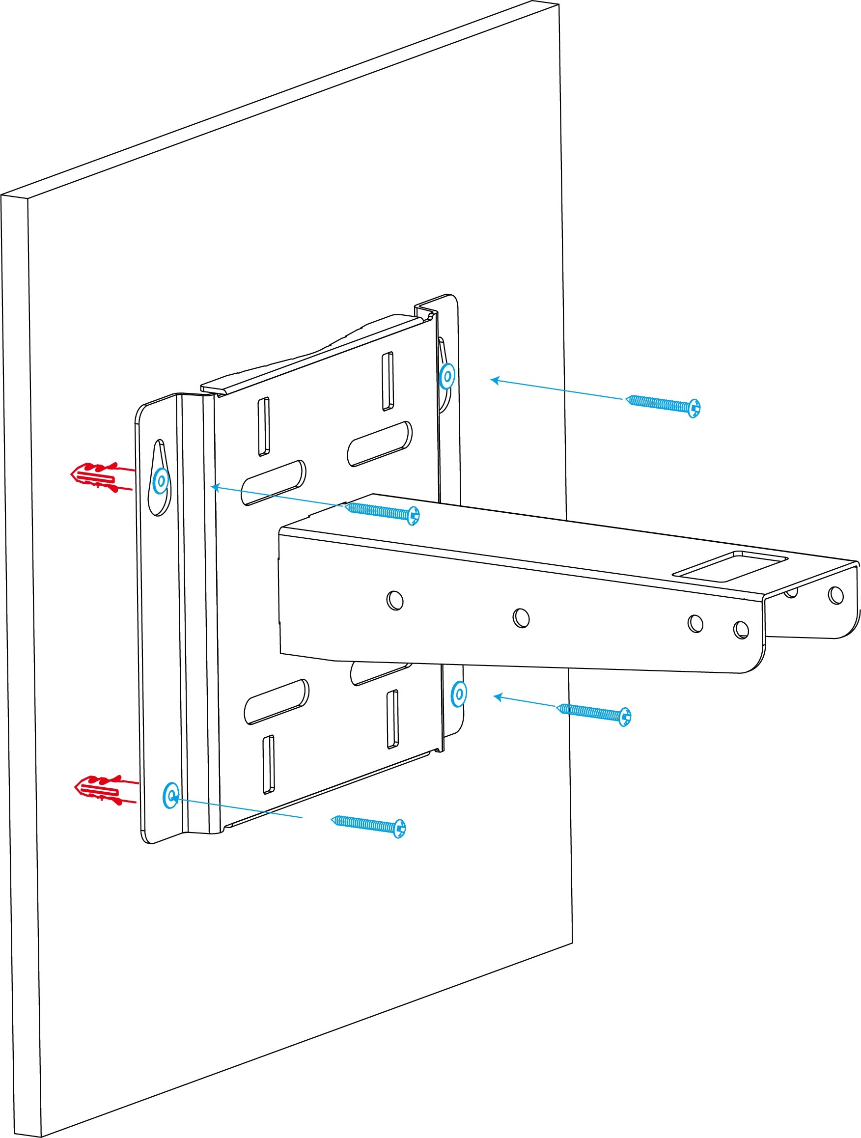
- Align the mounting bracket horizontally to the target surface, use a pencil to
mark four mounting holes.
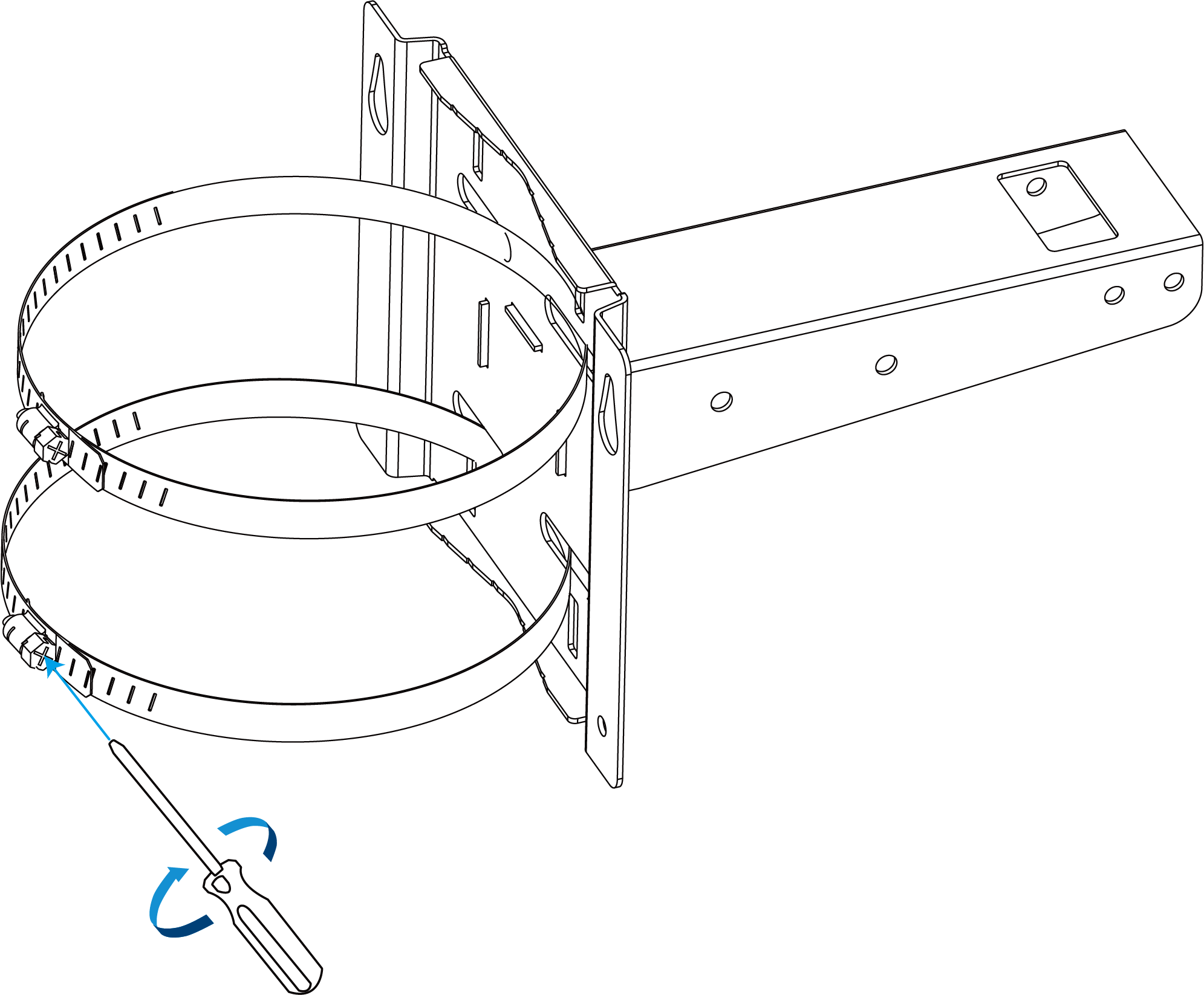
- Pole Mounting
-
- Straighten the hose clamps and slide them through the rectangular rings in the mounting bracket.
- Wrap the hose clamps around the pole.
- Use a screwdriver to tighten the locking mechanism clockwise.
Install the Solar Panel
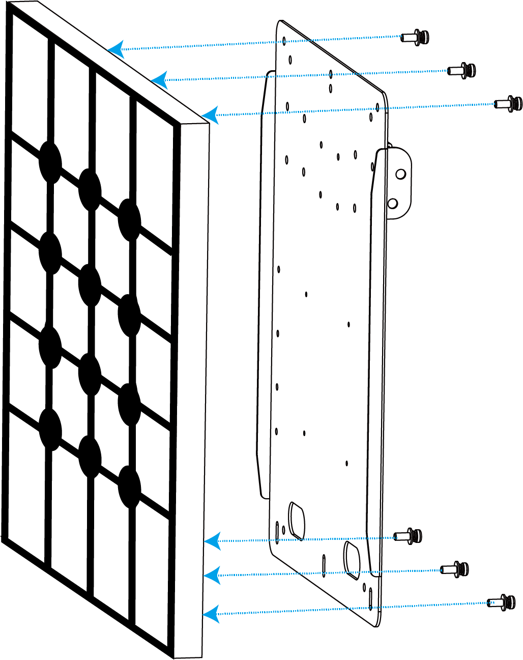
- Remove the protective plastics from the four corners of the solar panel.
- Secure the solar panel to the solar panel bracket with six fixing screws.
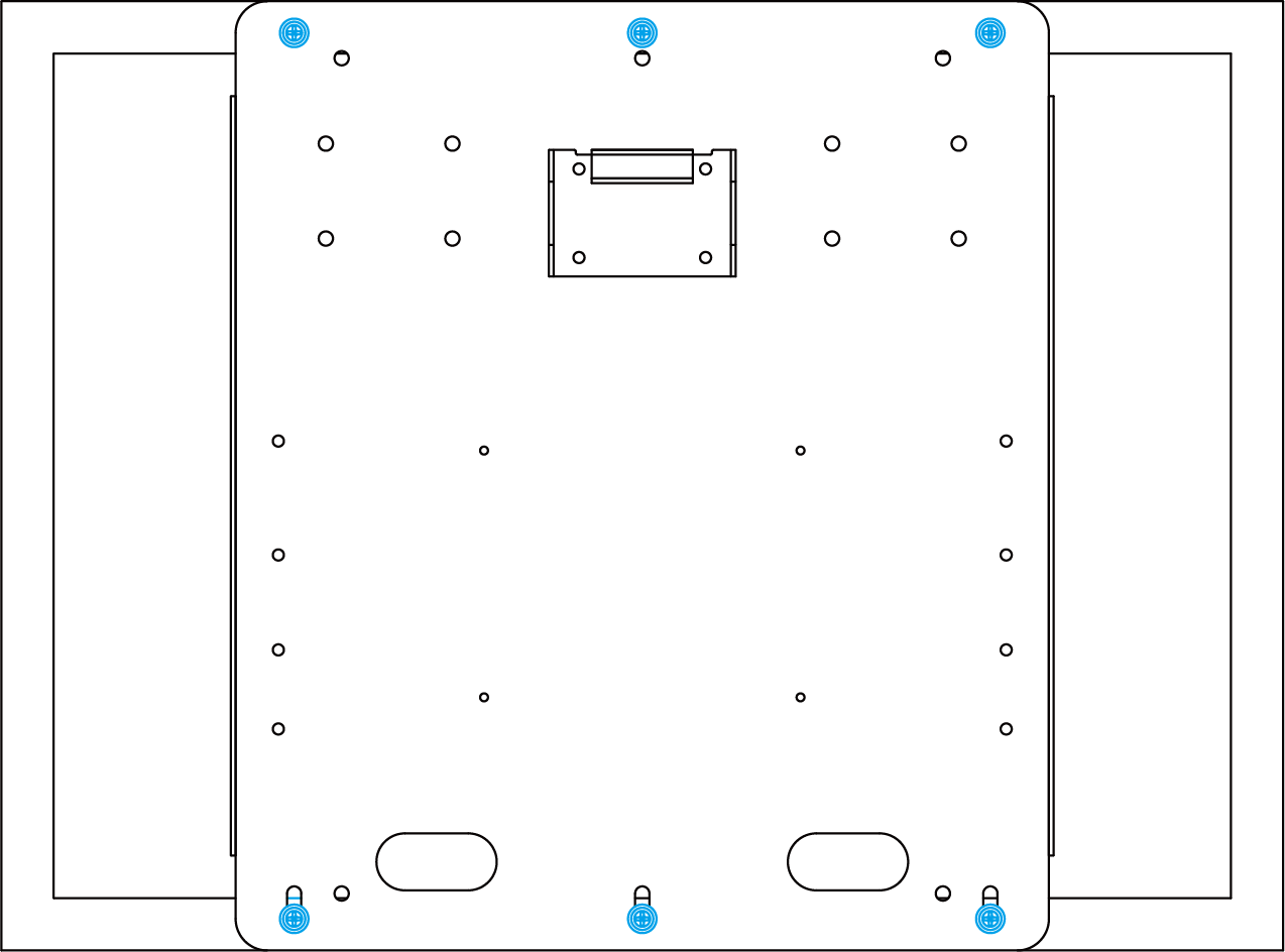
- Hang the solar panel bracket on the mounting bracket and secure the two parts with two fixing screws first.
- Adjust the solar panel bracket angle according to the installation environment. The
supported installation angles are 15°, 45°, and 75°.
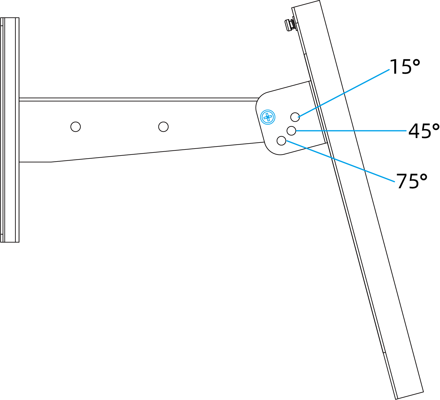
- Install the remaining two screws to secure the solar panel bracket.
Mount the Gateway
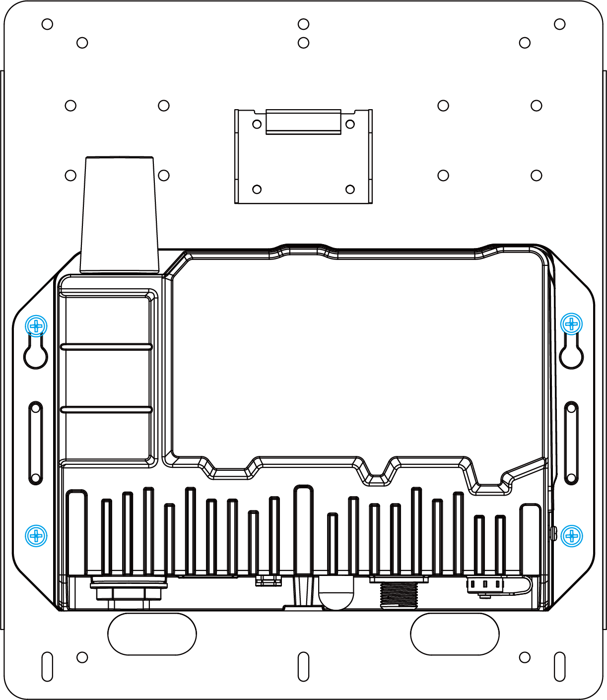
- Secure the gateway to the opposite side of the solar panel bracket with four screws. It
is suggested to install the two upper screws first.
- Install the LoRaWAN® antenna using one of the supported mounting methods.
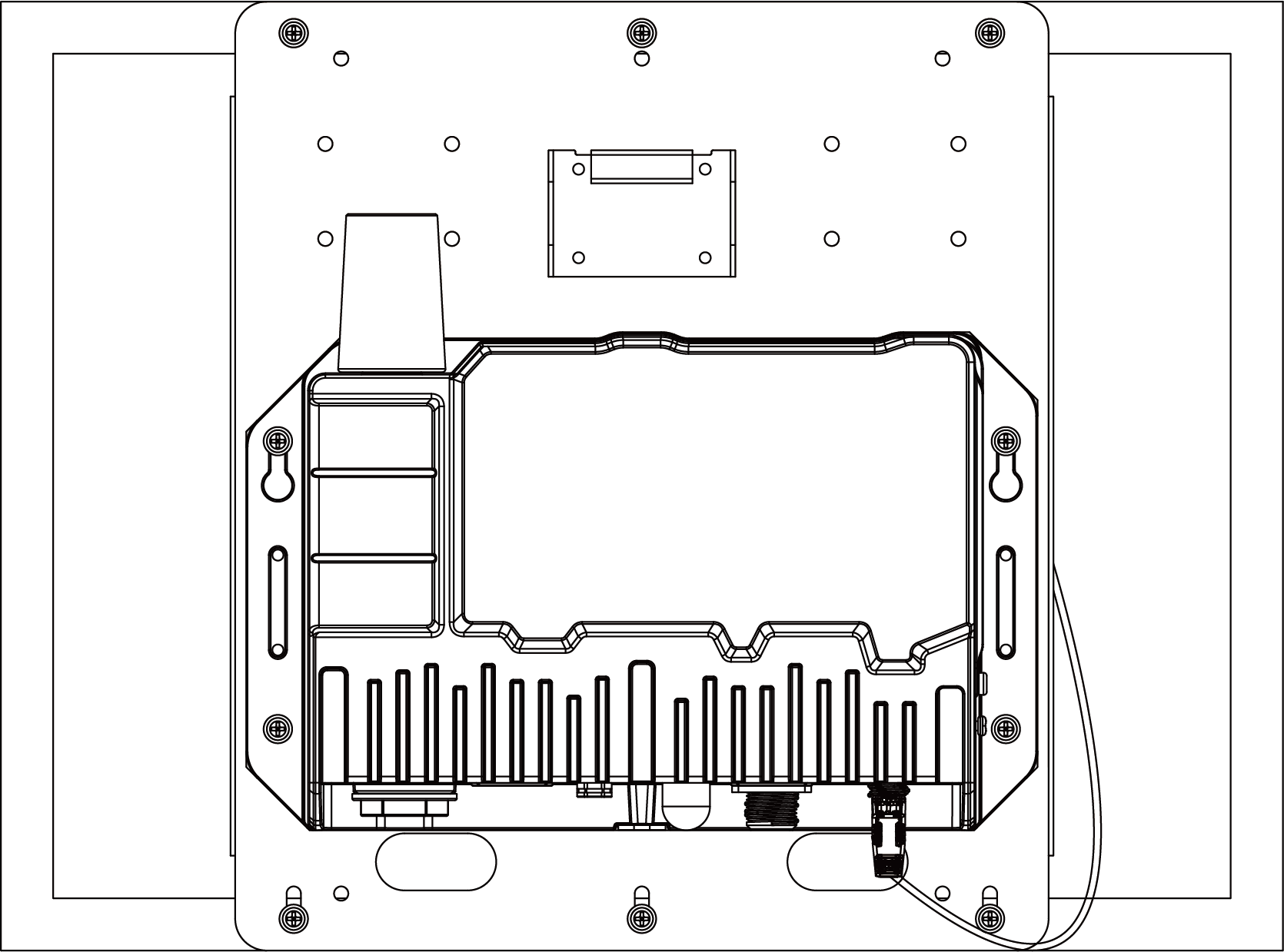
- After completing the required hardware installation, connect the M12 power cable of the
solar panel to the DC power connector. The gateway powers on automatically.
Install the LoRaWAN® Antenna
Select the U-strap or U-bolt mounting method according to the deployment.
- U-strap Mounting
-
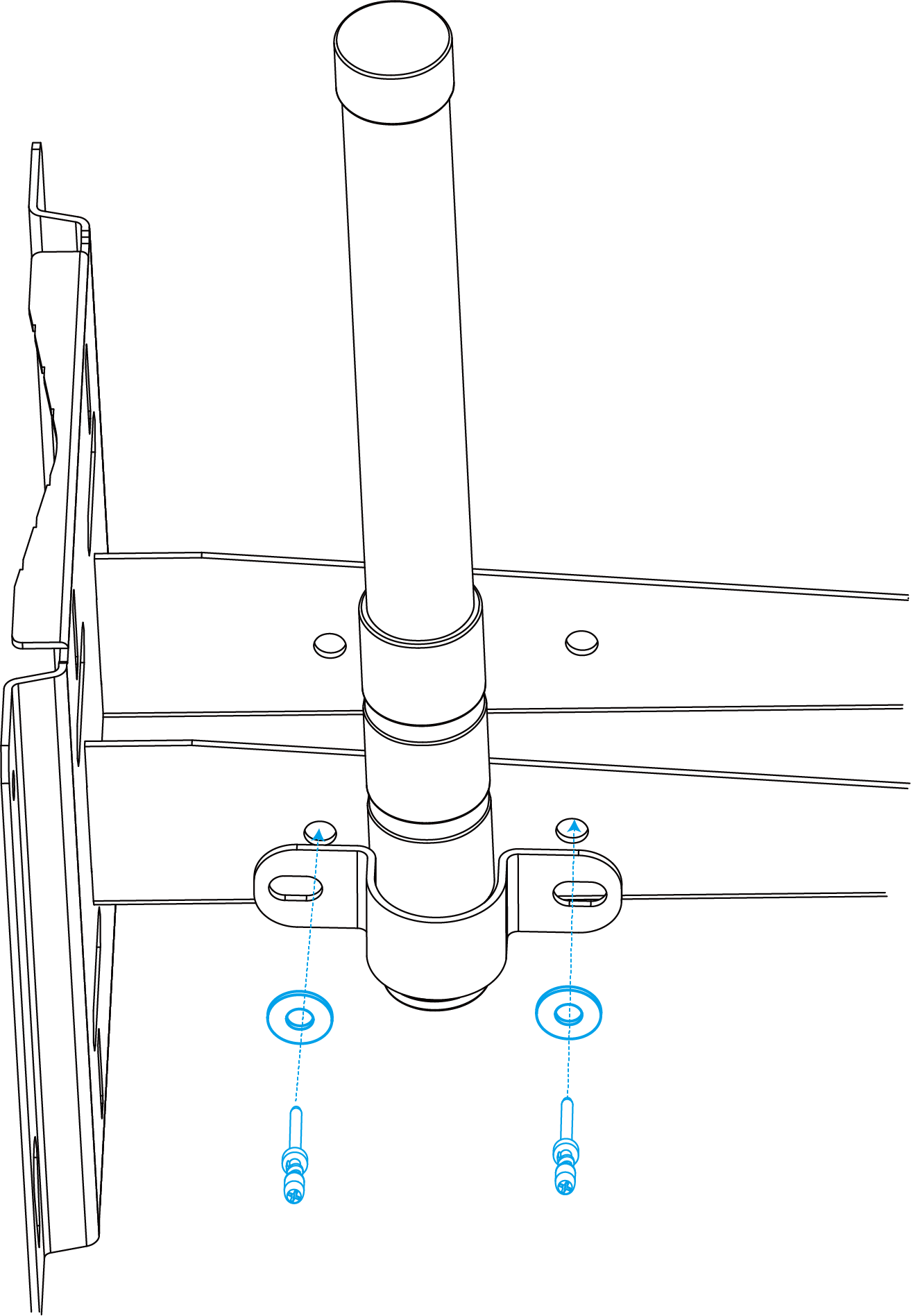
- Pass the LoRaWAN® antenna through the U-strap clamp.
- Secure the U-strap clamp to the side of the mounting bracket with two flat washers
and two screws.
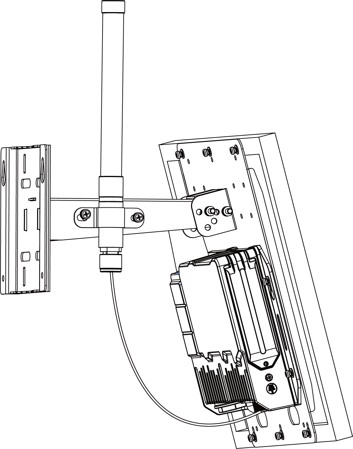
- Connect one end of the antenna coaxial cable to the LoRaWAN® antenna
and the other end to the gateway antenna connector.
- U-bolt Mounting
-
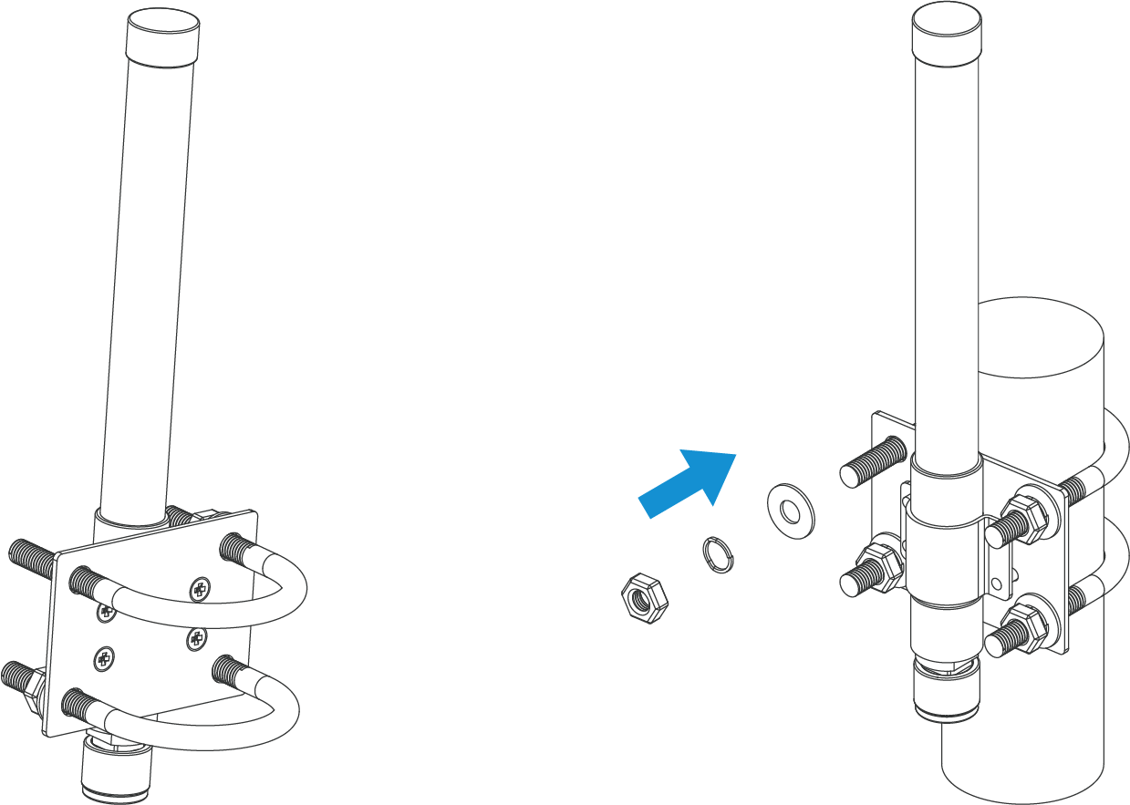
- Pass the LoRaWAN® antenna through the antenna clamp and secure it with four screws.
- Wrap the U-bolt around the pole and secure the clamp with the nuts and other
accessories.
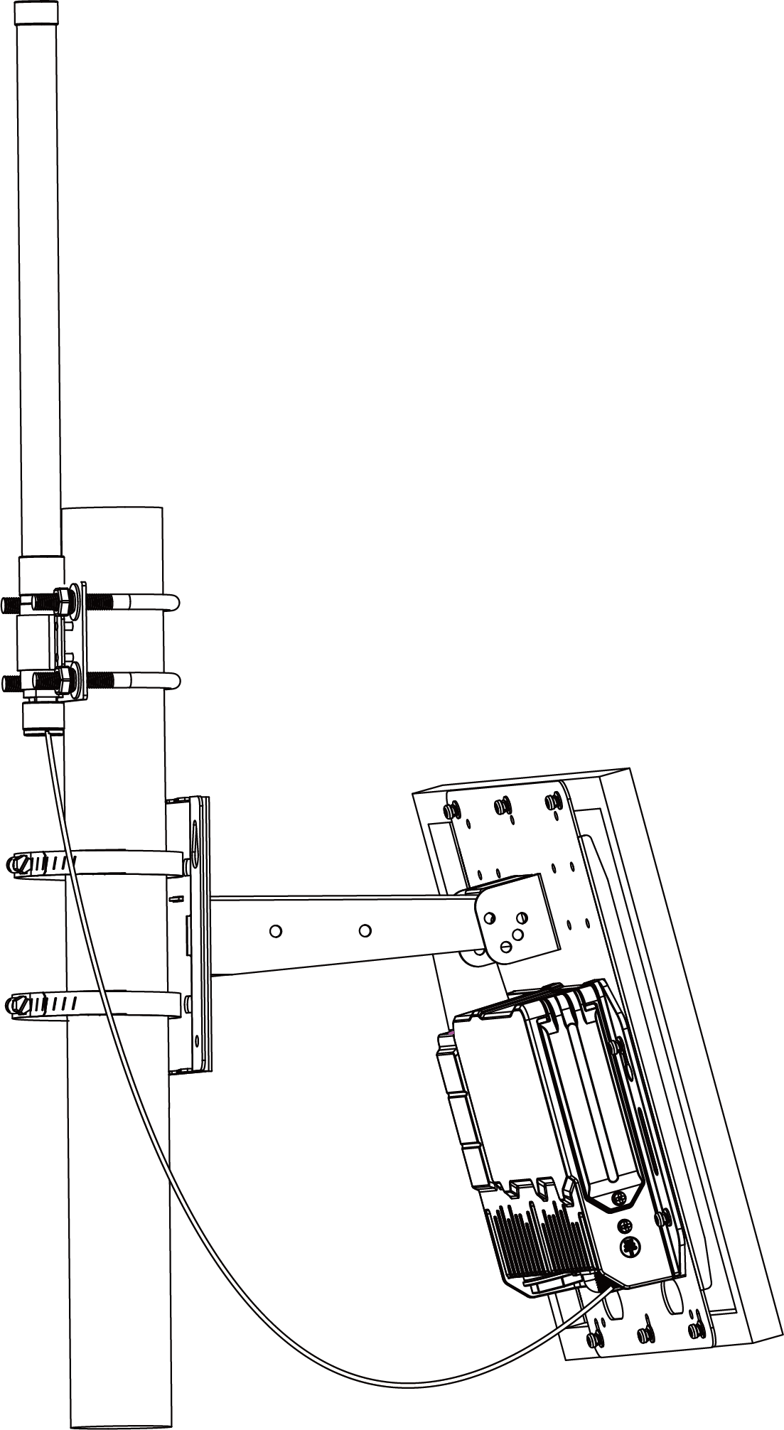
- Connect one end of the antenna coaxial cable to the LoRaWAN® antenna
and the other end to the gateway antenna connector.Tip: For better antenna signal, it is suggested to install the antenna at the top of the metal pole.
Weatherproof the Antenna Connection
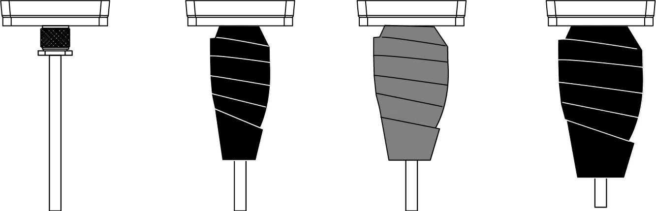
Cover the antenna connector with tape to protect the outdoor connection from bad weather.
Prerequisites: Electrical Insulation Tapes, 3M Waterproof TapesNote: Install the lightning arrester on the connector before wrapping the tapes if
required.
- Make sure the antenna is installed tightly and clean the connector surfaces.
- Wrap one layer of electrical insulation tape tightly around the connector, overlapping the previous wrap by 50%.
- Wrap one layer of 3M waterproof tape tightly around the connector, overlapping the previous wrap by 50%. Stretch the waterproof tape to twice its length while wrapping.
- Wrap one final layer of electrical insulation tape around the connector with natural uncoiling force, overlapping the previous wrap by 50% and covering the head and tail of the connector.
Lightning Protection and Grounding
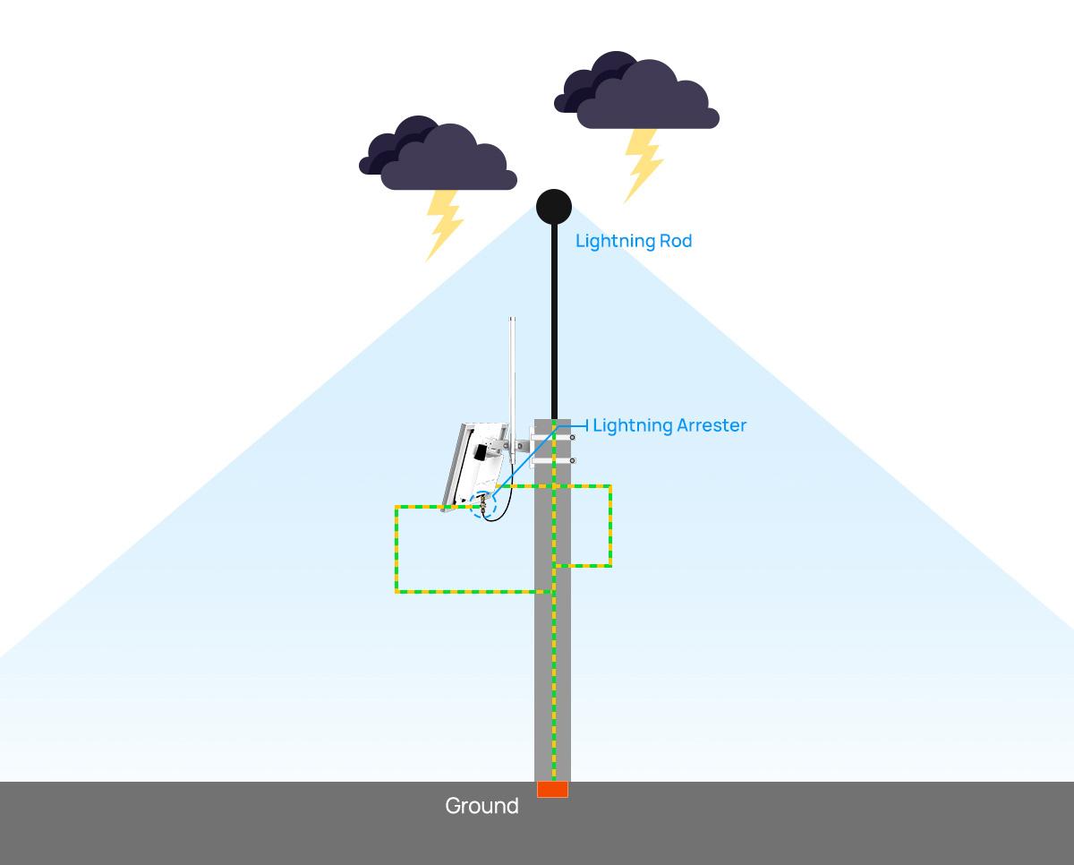
Take lighting protection measures, including but not limited to:
- Connect the gateway to earth ground.
- Add a lightning arrester to the antenna connector.
- Make sure the antennas are lower than the highest position of the building and the gateway and antennas are within the protection range of the lightning rod.
- If there is no lightning rod nearby, make sure the gateway is not installed in an area influenced by lightning, or install a lightning rod above the antennas.
- The cross-sectional area of the earthing wire should be more than 10 AWG.