Hardware Introduction
This chapter describes the hardware design of the device.
Hardware Overview
The following figure shows the main components of the device.
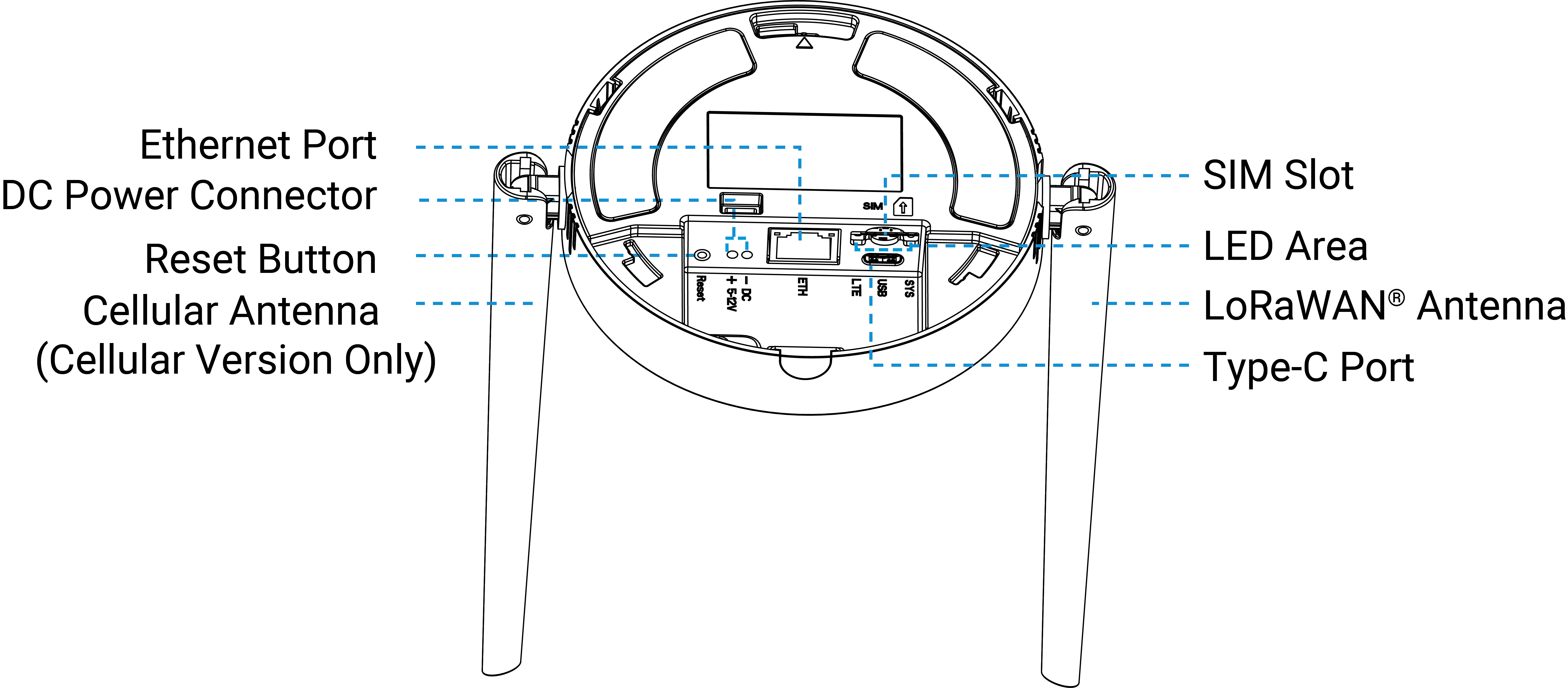
| Part | Description |
|---|---|
| Ethernet Port | Allows connection to an ISP for network access. |
| DC Power Connector | Supply DC power to the device. |
| LoRaWAN® Antenna | Enhance wireless communication range and reliability. |
| Cellular Antenna | |
| SIM Slot | Allows to insert a SIM card to connect to the cellular network. |
| LED Indicator | See LED Patterns. |
| Reset Button | Allows to reset the device to factory defaults. For details see LED Patterns. |
| Type-C Port | Used for device console or device power supply. |
LED Patterns
| LED | Status | Description |
|---|---|---|
| SYS | Off | The power is switched off |
| Green Static On | The power is switched on and the system is working well | |
| Red Static On | The power is switched on and the system malfunctions | |
| Static On → Quickly Blinks | Factory Reset: Press and hold the reset button for more than 5 seconds | |
| LTE | Off | SIM card is registering or failed to register (or there are no SIM cards inserted) |
| Slowly Blinks | SIM card has been registered and is ready for dial-up | |
| Quickly Blinks | SIM card has been registered and is dialing up now | |
| Static On | SIM card has been registered and dialed up successfully | |
| Ethernet Port - Link Indicator (Yellow) | Off | Disconnected or connection failure |
| Blinks | Transmitting data | |
| Ethernet Port - Rate Indicator (Green) | Off | Ethernet port is disconnected |
| On | Ethernet port is connected |
Device Dimensions
The following figure shows the device dimensions (unit:mm).