UG63 Quick Start Guide
Overview
Packing List
 |
 |
 |
|
1 × UG63 Gateway |
2 × Wall Mount Kits |
1 × Warranty Card |
 |
||
| 1 × Quick Guide Card |
 |
 |
|
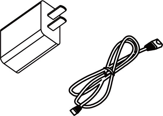
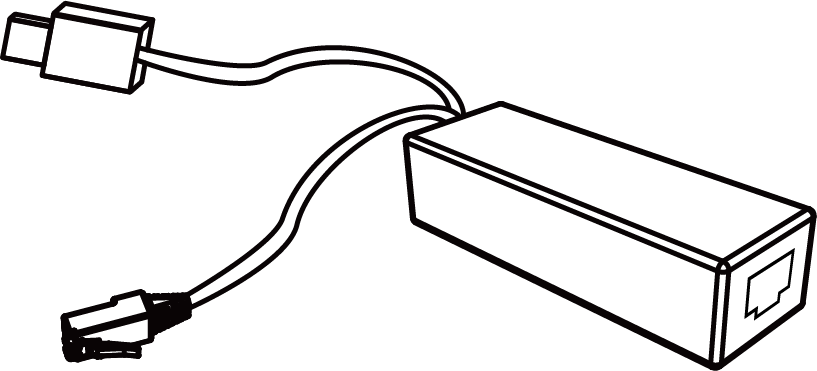
| 1 × Type-C Cable (1m) & Power Adapter | 1 × PoE Splitter |
Hardware Introduction
This chapter describes the hardware design of the device.
Hardware Overview
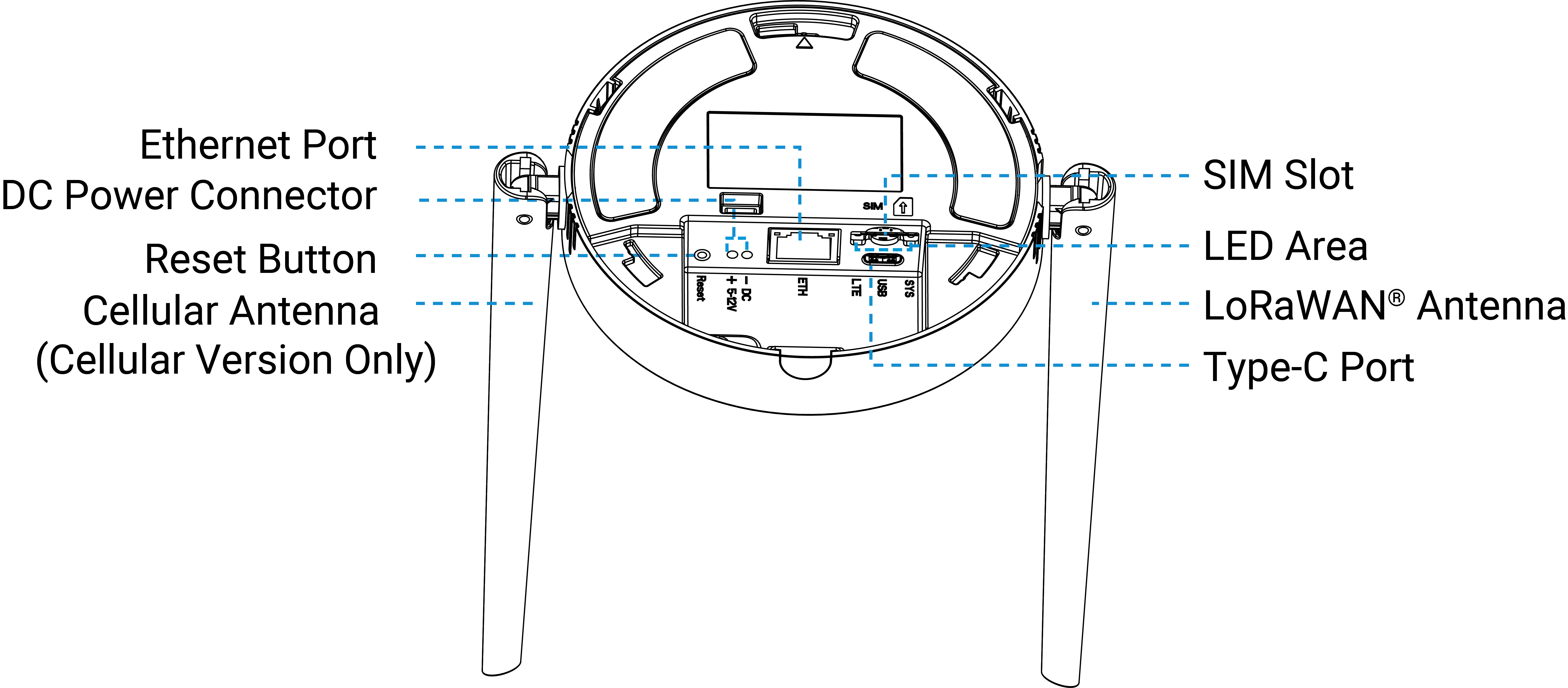
| Part | Description |
|---|---|
| Ethernet Port | Allows connection to an ISP for network access. |
| DC Power Connector | Supply DC power to the device. |
| LoRaWAN® Antenna | Enhance wireless communication range and reliability. |
| Cellular Antenna | |
| SIM Slot | Allows to insert a SIM card to connect to the cellular network. |
| LED Indicator | See LED Patterns. |
| Reset Button | Allows to reset the device to factory defaults. For details see LED Patterns. |
| Type-C Port | Used for device console or device power supply. |
LED Patterns
| LED | Status | Description |
|---|---|---|
| SYS | Off | The power is switched off |
| Green Static On | The power is switched on and the system is working well | |
| Red Static On | The power is switched on and the system malfunctions | |
| Static On → Quickly Blinks | Factory Reset: Press and hold the reset button for more than 5 seconds | |
| LTE | Off | SIM card is registering or failed to register (or there are no SIM cards inserted) |
| Slowly Blinks | SIM card has been registered and is ready for dial-up | |
| Quickly Blinks | SIM card has been registered and is dialing up now | |
| Static On | SIM card has been registered and dialed up successfully | |
| Ethernet Port - Link Indicator (Yellow) | Off | Disconnected or connection failure |
| Blinks | Transmitting data | |
| Ethernet Port - Rate Indicator (Green) | Off | Ethernet port is disconnected |
| On | Ethernet port is connected |
Device Dimensions

Powering Options
This chapter describes the powering supply option supported by UG63 gateways. Please select one of the following options to power the gateway.
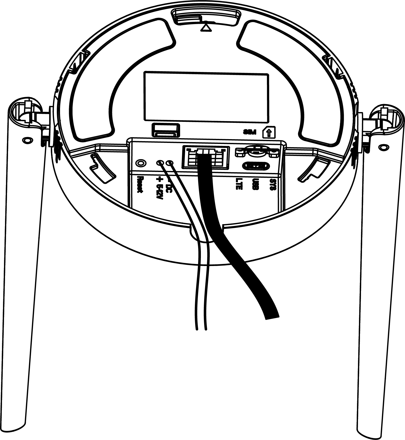
- Powered by DC Power Connector
- The gateway can be powered by a DC power connector (5-12V DC).
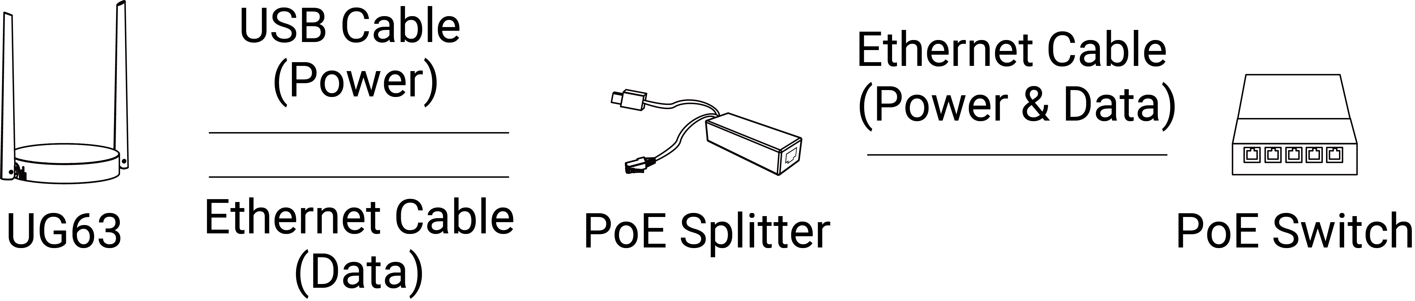
- Powered by Active PoE
- The Ethernet port can receive power from PoE source by connecting to an
802.3af standard PoE splitter.
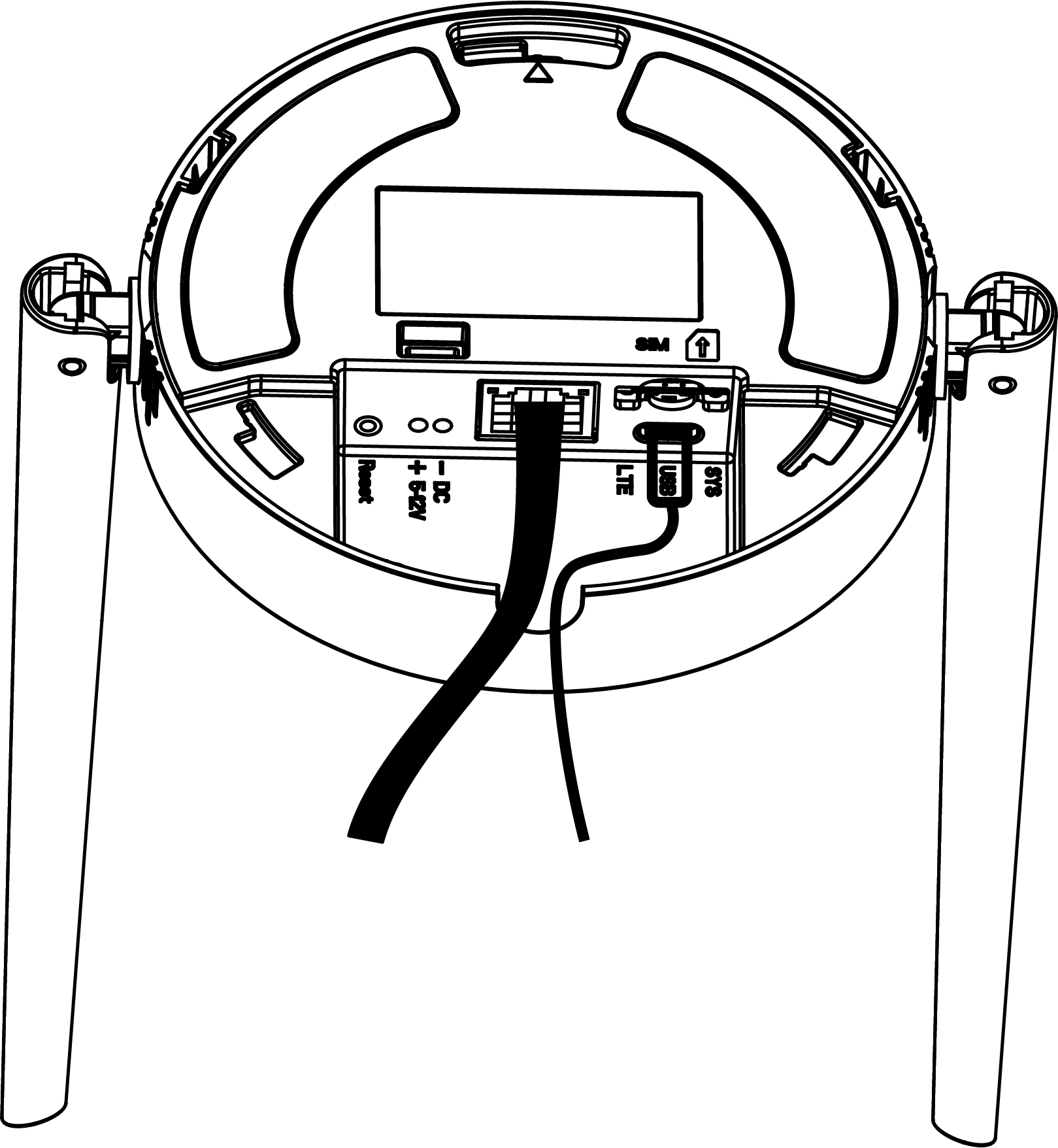
- Powered by USB Type-C
- The gateway can be powered by a USB Type-C port (5V DC/2A).
Installation Instructions
This chapter provide instructions on how to install the accessories and the device.
SIM Card Installation (Cellular Version Only)
This section describes how to install a SIM card into the device. If not needed, please skip this section.
- The gateway supports cellular feature (model name includes
-Lxxx). - A SIM card (Micro-3FF).
- Insert the SIM card into the SIM slot in the correct orientation.
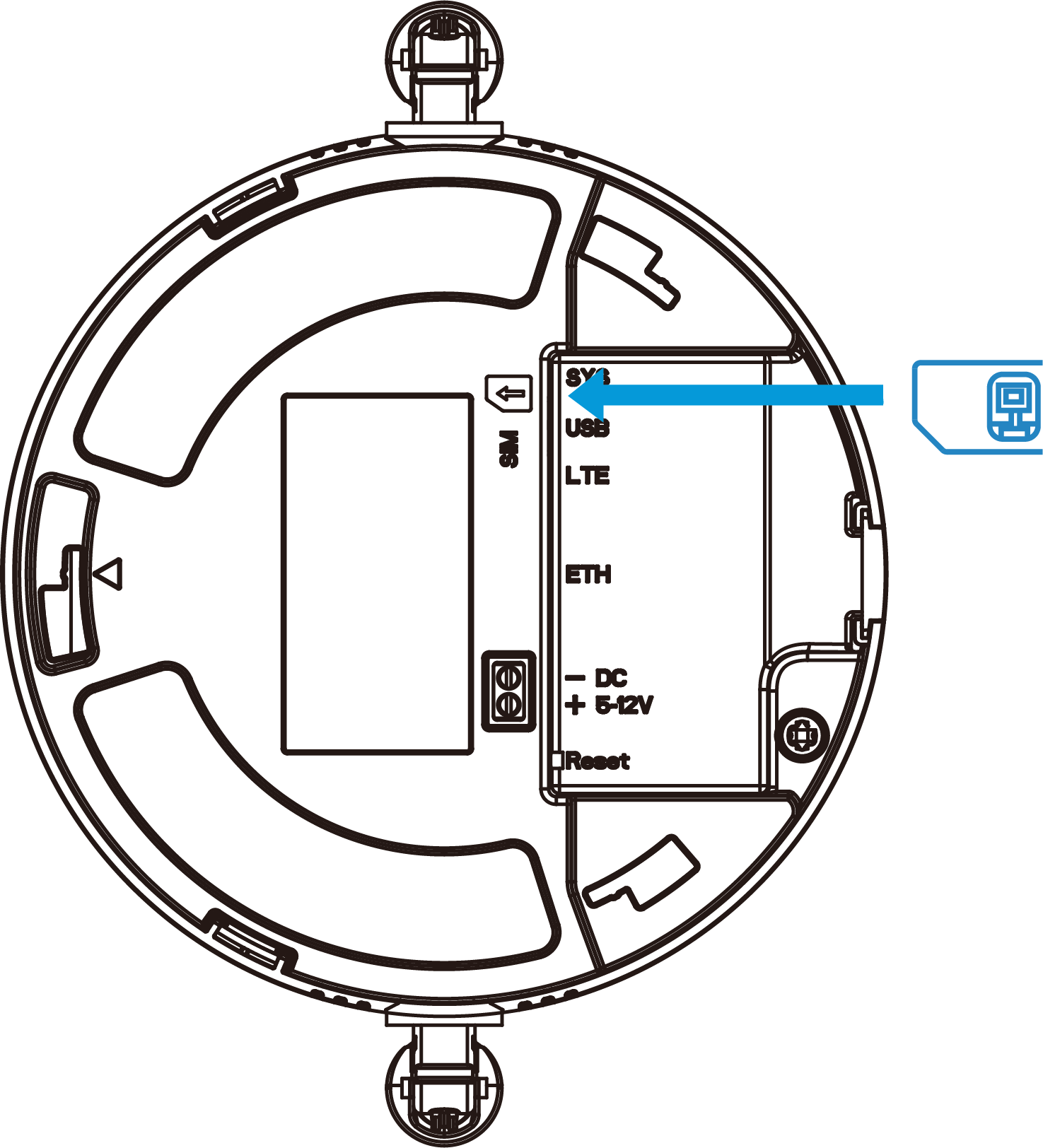
To remove the SIM card, press it and it will pop up automatically.
Gateway Installation
- Desktop
- Steps:
- Take off the cable groove cover and mounting plate on the back of the device.
- Connect the cables to the device, then pass the connected cables through the groove.
- Place the device on the desktop.
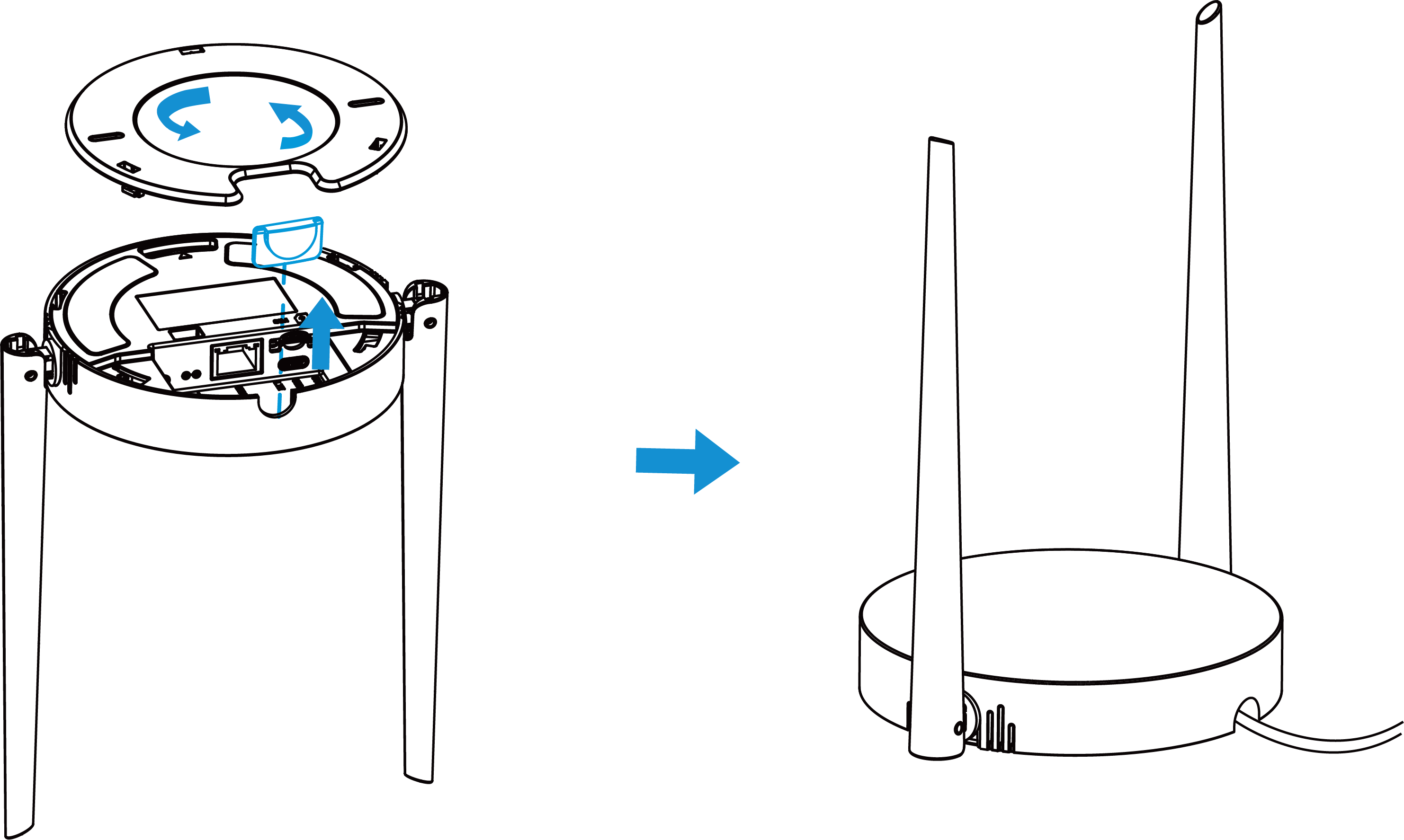
- Wall/Ceiling Mounting
-
Requirements:
- The wall structure shall be sufficiently solid and stable to ensure firm screw fixation and overall mounting stability.
- Screw mounting positions must avoid internal wall electrical wiring, water pipes and other concealed utilities to prevent structural damage and potential safety hazards.
Prerequisites: Screwdriver, Wall Mount Kit, Drill
Steps:
- Take off the mounting plate on the back of the device.
- Drill two holes in the wall/ceiling aligned with the wall-mount holes of the mounting plate.
- Insert the wall plugs into the drilled holes.
- Fasten the mounting plate to the wall plugs with the supplied
wall mounting screws.
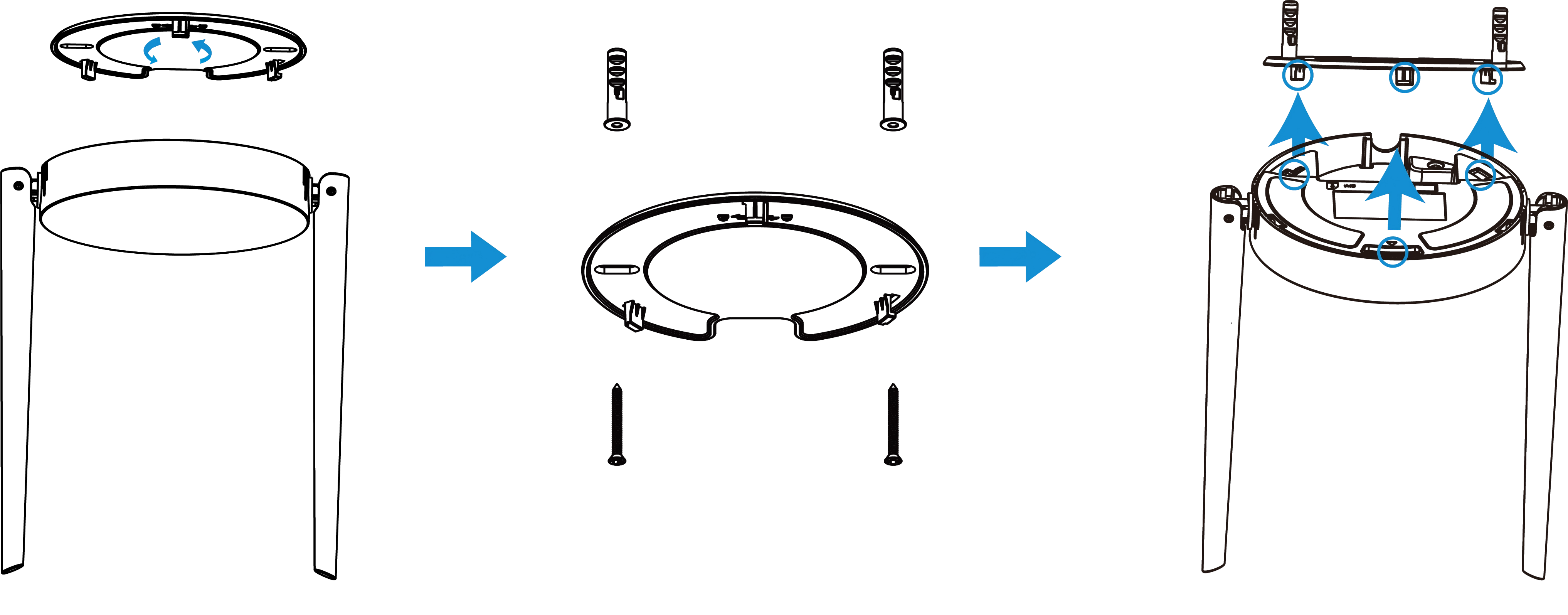
- Connect the cables to the device, then pass the connected cables through the groove.
- Turn the device clockwise to lock it to the mounting
plate.
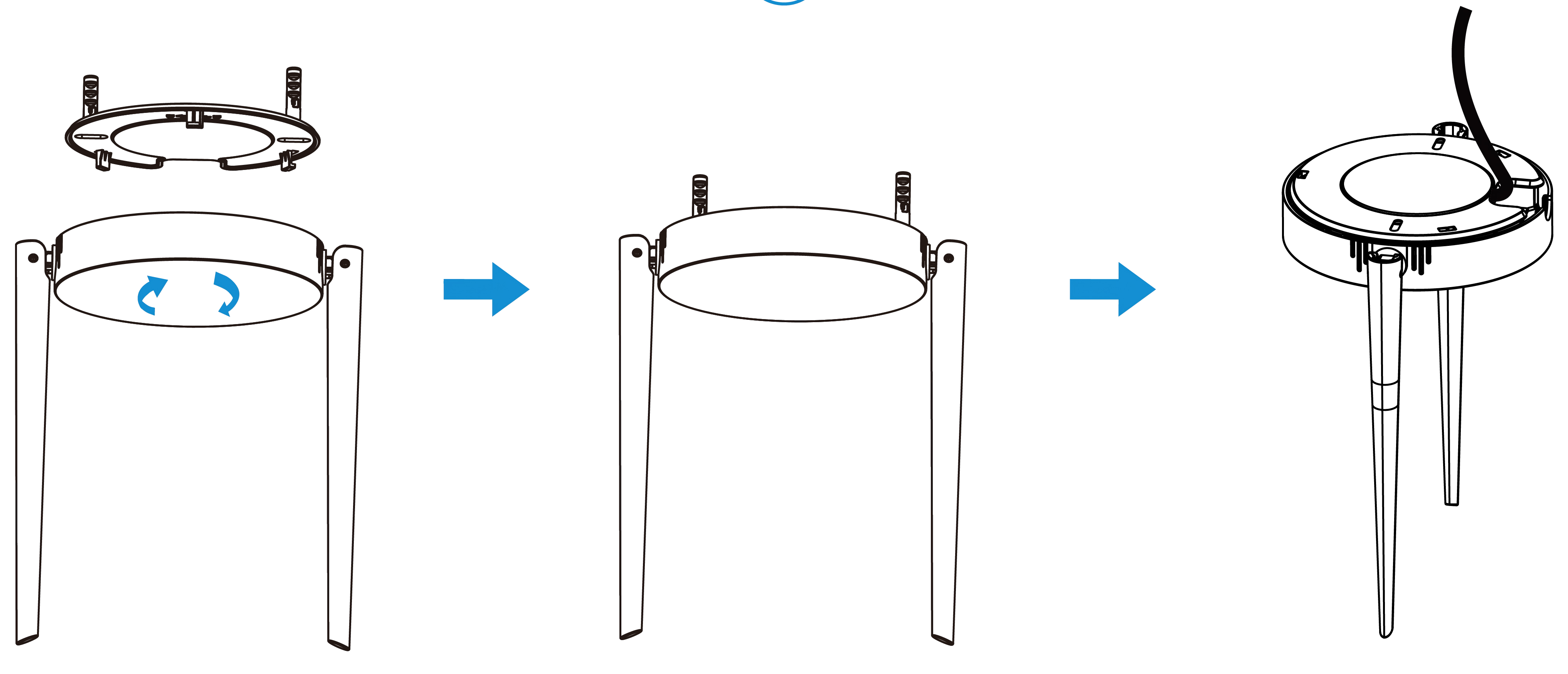
Access the Gateway
The device provides a web GUI for configuration. This chapter describes how to access the device's web GUI for the first time.
- Enable the Wireless Network Connection on your computer, search for the corresponding for Wi-Fi SSID, and connect to it. Default Wi-Fi SSID: Gateway_XXXXXX (last 6 digits of the Wi-Fi MAC address)
- Open a web browser (Chrome is recommended) and type in https://192.168.1.1 to access the web GUI.
- Log in to the web GUI using the default
credentials:
Username: admin
Password: password - After logging the web GUI for the first time, it is
necessary to change the default password.
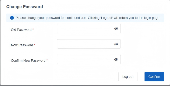
- Enter the old password.
- Enter a New Password. The password must contain at least one letter and one number.
- Enter Confirm New Password.
- Click Confirm.
- Log in to the web GUI using the new credentials.
FCC Statement
Any changes or modifications not expressly approved by the party responsible for compliance could void the user’s authority to operate the equipment. This device complies with part 15 of the FCC Rules. Operation is subject to the following two conditions:
(1) This device may not cause harmful interference, and.
(2) This device must accept any interference received, including interference that may cause undesired operation.
Note: This equipment has been tested and found to comply with the limits for a Class B digital device, pursuant to part 15 of the FCC Rules. These limits are designed to provide reasonable protection against harmful interference in a residential installation. This equipment generates, uses and can radiate radio frequency energy and, if not installed and used in accordance with the instructions, may cause harmful interference to radio communications. However, there is no guarantee that interference will not occur in a particular installation. If this equipment does cause harmful interference to radio or television reception, which can be determined by turning the equipment off and on, the user is encouraged to try to correct the interference by one or more of the following measures:
—Reorient or relocate the receiving antenna.
—Increase the separation between the equipment and receiver.
—Connect the equipment into an outlet on a circuit different from that to which the receiver is connected.
—Consult the dealer or an experienced radio/TV technician for help.
FCC Radiation Exposure Statement:
This equipment complies with FCC radiation exposure limits set forth for an uncontrolled environment. This equipment should be installed and operated with minimum distance 20cm between the radiator& your body. This transmitter must not be co-located or operating in conjunction with any other antenna or transmitter.
Related Resource
For more information, please refer to Milesight Document Center.