Hardware Installation
This chapter describes the preparation and installation procedures for mounting the controller and its accessories at the deployment site.
Warning: Before installation, ensure the controller and the
air conditioner are powered off!
Installation Requirement
- Installation Locations
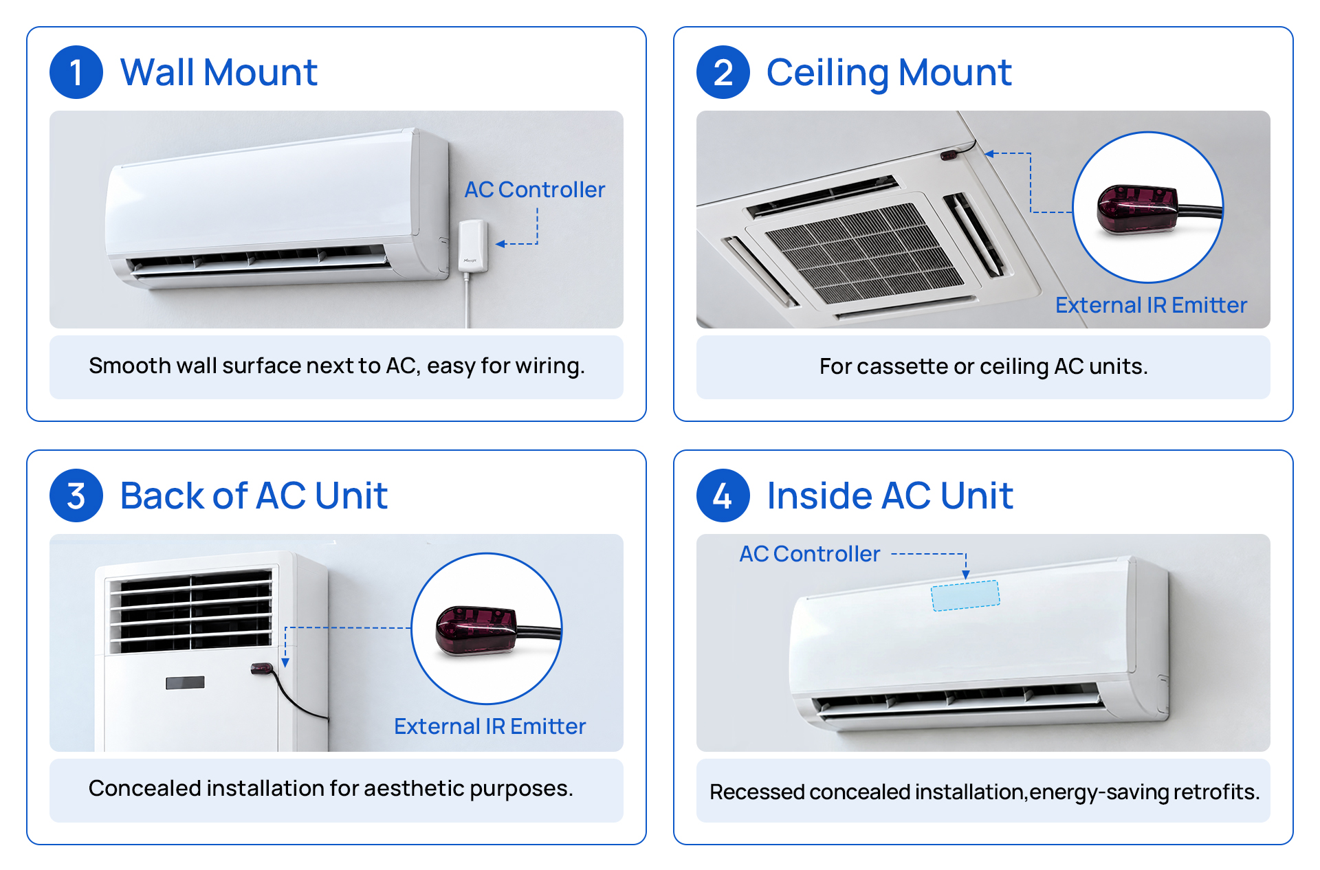
- The controller supports multiple installation locations to suit different on-site
environment:
 Tip:
- For wall mount, the controller's installation height should not exceed AC unit height, and preferably not less than 2 meters.
- Make sure the controller is within the transmission range of the LoRaWAN gateway and with no metal objects nearby.
- It is recommended that the controller be placed within 5 meters of the air conditioner (up to a maximum of 10 meters) and pointed toward the air conditioner.
- It requires both external NTC sensor and external IR emitter when installing inside or at the back of the air conditioner.
- Installation Method
- The controller offers two categories of installation methods:Surface InstallationConcealed Installation
Method Suitable Surface Description Screw Mount Non-smooth surfaces (wood, concrete, etc.) For long-term installation. Before installation, check for concealed wiring and pipes 3M Tape Mount Dry, smooth, solid, clean surface (painted walls, glass, etc.) For fast and easy installation. Recommended application temperature: 20-40°C. In low temperatures, pre-warm the tape to approximately 30°C. AC Type Installation Position Wall-mounted Split Embedded in the unused drain pipe position of the indoor unit Cassette/Ceiling AC Concealed inside the cassette decorative panel or within the gypsum ceiling Floor-standing Cabinet AC Concealed at the back of the indoor unit - Environmental Conditions
-
- Do not cover the controller surface, as this will disable the built-in IR and temperature sensors.
- Avoid installation in direct sunlight or spotlight to reduce interference with IR signals.
- When using battery compartment, operating ambient temperature should be 0 - 40°C.
External Accessories Selection
The controller supports various external accessories to extend functionality and adapt to
different installation scenarios. All accessories below are sold separately.
| Accessory | When to Use |
|---|---|
| NTC Sensor |
|
| Current Transformer |
Note: It is primarily for checking AC on/off status and
rough current measurement; it cannot perform precise power consumption
testing.
|
| IR Emitter |
|
| Battery Compartment |
|
Prerequisites
- Check AC Compatibility
- Confirm the AC brand is in the compatibility list and IR code learning verification is completed.
- Check the Installation Conditions
-
Select the required mounting method and prepare the corresponding mounting accessories.
- Check the External Sensors
- Make sure the external sensors are connected to the controller and functioning properly.
- Check the Power Supply
- The controller can be powered by a DC power supply (3.6 to 7 V) or an optional battery
compartment using the USB port. For battery power, make sure the battery compartment,
its accessories, and three new AA 1.5V batteries (Recommended Brands: Duracell,
Energizer, Panasonic) are ready.CAUTION: Do not overload the device, otherwise it may cause the permanent damage.
- Complete the Initial Test
- Ensure the controller is tested well with the air conditioner and other necessary devices:
Install the External Sensors (Optional)
- Insert the External sensors
-
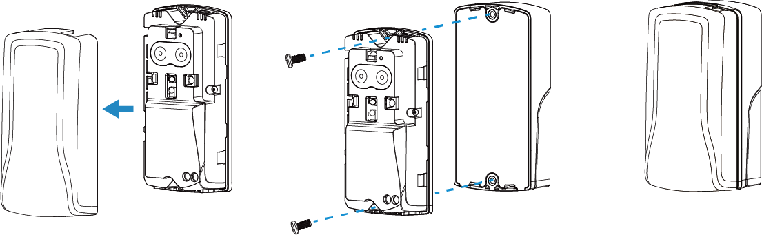
- Remove the controller front cover.
- Connect the external sensors to the corresponding interfaces of the
controller.
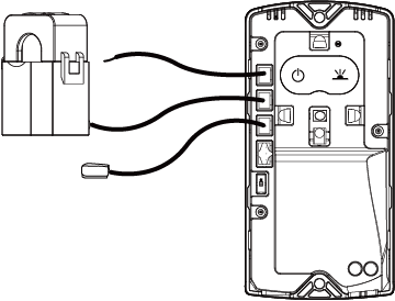
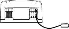
- Restore the front cover and pass the sensor cables through the holes at the top
of the controller cover.
- Install the IR Emitter
- Typically, the IR emitter can be mounted within the IR-available range of air
conditioner with cable clips. The installation method depends on your requirement:
- Parallel Installation: Stick the IR emitter head near the AC IR receiver. This will not affect normal use of the original remote control.
- Interventional Installation: Use the included IR-blocking tape to secure the IR emitter head onto the AC IR receiver, so the emitter sits between the tape and the receiver. In this way, original remote control becomes largely unusable and it is suitable for scenarios requiring centralized control.
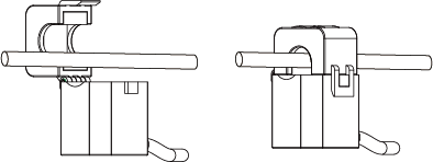
- Install the Current Transformer
-
- Open the current transformer to clip it around a single Live wire. Make sure the direction of the current matches the arrow on the current transformer, which flows from the outlet to the air conditioner.
- Close the clip with a slight “click” sound to make sure the clip firmly grips
the wire.
- Install the NTC Sensor
- Mount the NTC sensor with cable clips. The installation position depends on your
measuring requirement:
- Ambient Temperature Detection: Place the sensor in a well-ventilated indoor area.
- Outlet Temperature Detection: Fix the sensor near the AC air outlet to check air conditioner on/off status.
Prepare and Install the Battery Compartment (Optional)
If the controller requires battery power, follow the steps to install the batteries into the compartment, and deploy the battery compartment.
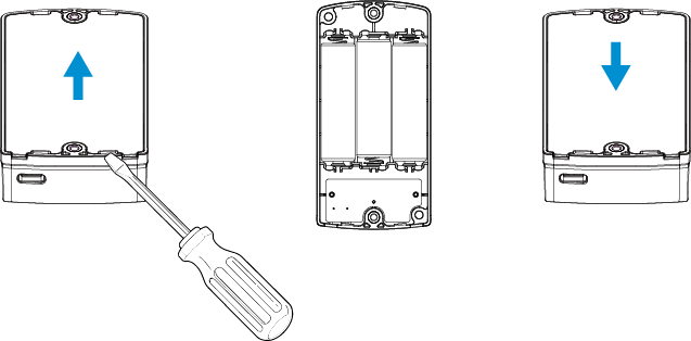
- Install Batteries into the Battery Compartment
-
- Remove the battery compartment cover using a screwdriver.
- Install the batteries into the battery compartment.Note: Ensure all batteries are new and of the same brand. Using old or mixed batteries may shorten battery life or cause inaccurate battery level calculation.
- Reinstall the battery compartment cover.
The battery compartment is typically mounted beside the controller. Select one of the
following mounting methods.
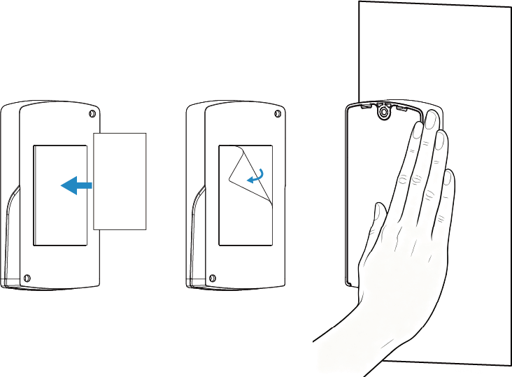
- Mount with 3M Tape
-
- Apply 3M tape to the back of the battery compartment, avoiding touching the adhesive side with your fingers.
- Remove the liner and position the device to the target surface.
- Press firmly for at least 30 seconds to ensure full adhesion.
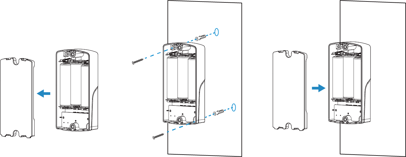
- Mount with Screws
-
- Remove the battery compartment cover.
- Drill two holes in the wall aligned with the wall-mount holes of the battery compartment.
- Insert the wall plugs into the drilled holes.
- Fasten the battery compartment to the wall plugs with the supplied wall mounting screws.
- Reinstall the battery compartment cover.
Install the Controller
Select one of the following mounting methods.
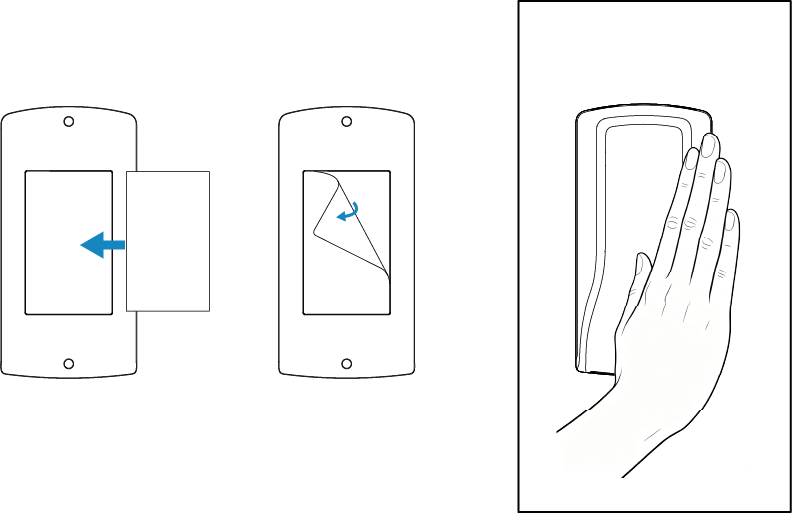
- Mount with 3M Tape
-
- Apply 3M tape to the back of the controller, avoiding touching the adhesive side with your fingers.
- Remove the liner and position the device to the target surface.
- Press firmly for at least 30 seconds to ensure full adhesion.
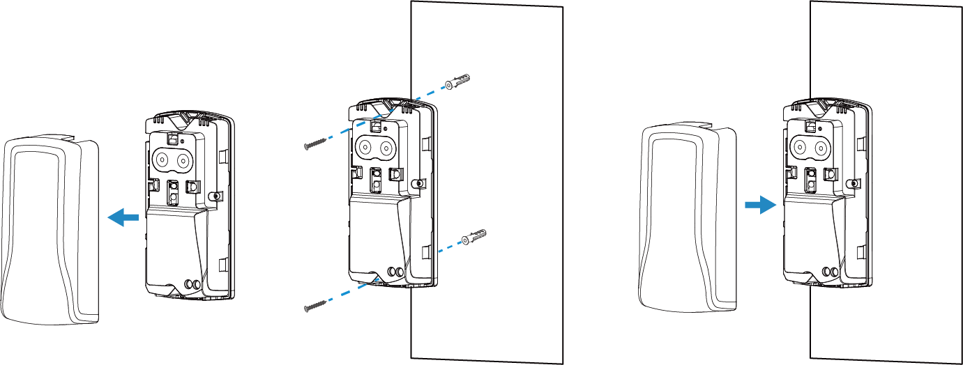
- Mount with Screws
-
- Remove the controller cover.
- Drill two holes in the wall aligned with the wall-mount holes of the controller.
- Insert the wall plugs into the drilled holes.
- Fasten the controller to the wall plugs with the supplied wall mounting screws.
- Reinstall the controller cover.
- Fixed onto the Battery Compartment
- For aesthetic reasons, the controller can be mounted on top of the battery
compartment.
- Remove the controller cover.
- Fasten the controller onto the battery compartment with the supplied screws.
- Reinstall the controller cover.