Hardware Introduction
This chapter describes the hardware design of the device.
Hardware Overview
The following figure shows the main components of the device.
- Bottom View
-
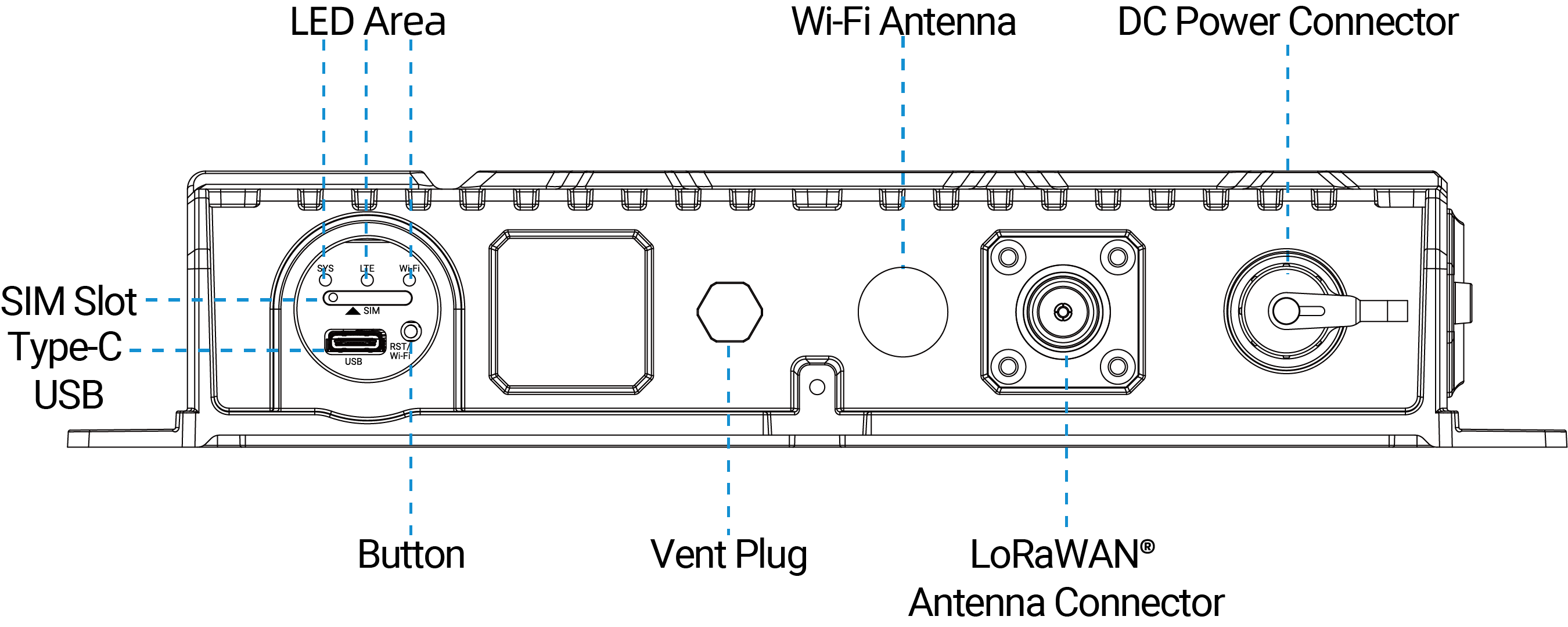
Part Description DC Power Connector Connect a solar panel or an external DC source to supply power to the device. LoRaWAN® Antenna Connector Allows connection of an external antenna to enhance wireless communication range and reliability. Wi-Fi Antenna Enhance wireless communication range and reliability. Vent Plug Equalizes the internal pressure and prevents moisture build-up. LED Area See LED Patterns. Button See Button Patterns. SIM Slot Allows to insert a SIM card to connect to the cellular network. Type-C USB Port Used for device console or device power supply.
- Side View
-
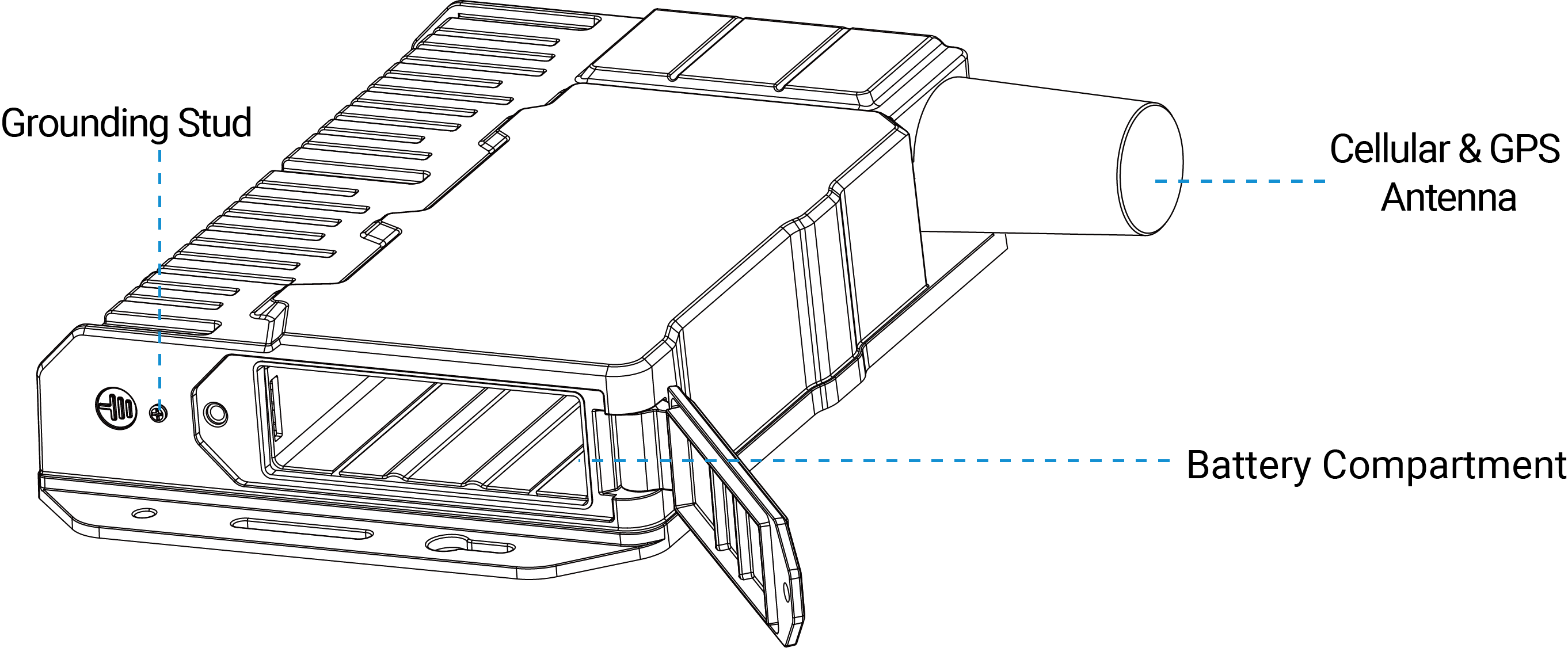
Part Description Cellular & GPS Antenna Enhance wireless communication range and reliability. Battery Compartment Install battery pack to supply power to the device. Grounding Stud Used to connect to an earth ground to protect the device from power surges.
LED Patterns
| LED | Status | Description |
|---|---|---|
| SYS | Off | The power is switched off or in sleep mode |
| Green Static On | The power is switched on and the system is working well | |
| Red Static On | The power is switched on and the system malfunctions | |
| LTE | Off | SIM card is registering or failed to register (or there are no SIM cards inserted) |
| Slowly Blinks | SIM card has been registered and is ready for dial-up | |
| Quickly Blinks | SIM card has been registered and is dialing up now | |
| Static On | SIM card has been registered and dialed up successfully | |
| Wi-Fi | Off | Wi-Fi is off |
| Slowly Blinks | Wi-Fi is starting | |
| Static On | Wi-Fi is on |
Button Patterns
| Function | Action | LED Status |
|---|---|---|
| Turn On Wi-Fi | When Wi-Fi is disabled, quickly press the button once to turn on Wi-Fi for 10 minutes. | Wi-Fi: Off → On |
| Turn Off Wi-Fi | When Wi-Fi is enabled, quickly press the button once to turn off Wi-Fi for 10 minutes. | Wi-Fi: On → Off |
| Enter Low Power Mode | When low power mode is enabled and the gateway detects not enough solar power. | SYS: Quickly Blinks → Off |
| Wake Up | Under low power mode, quickly press the button once to wake up for 10 minutes. | SYS: Off → On |
| Factory Reset | Press and hold the button for more than 5 seconds. | SYS: Quickly Blinks |
DC Power Connector Definition
The following table shows the pin definition of the DC power connector.
| Pin | Description | Figure |
|---|---|---|
| 1 | DC- |
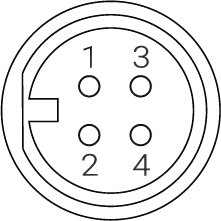 |
| 2 | DC+ | |
| 3 | Connect/disconnect the pins together to power on/off the device. | |
| 4 |
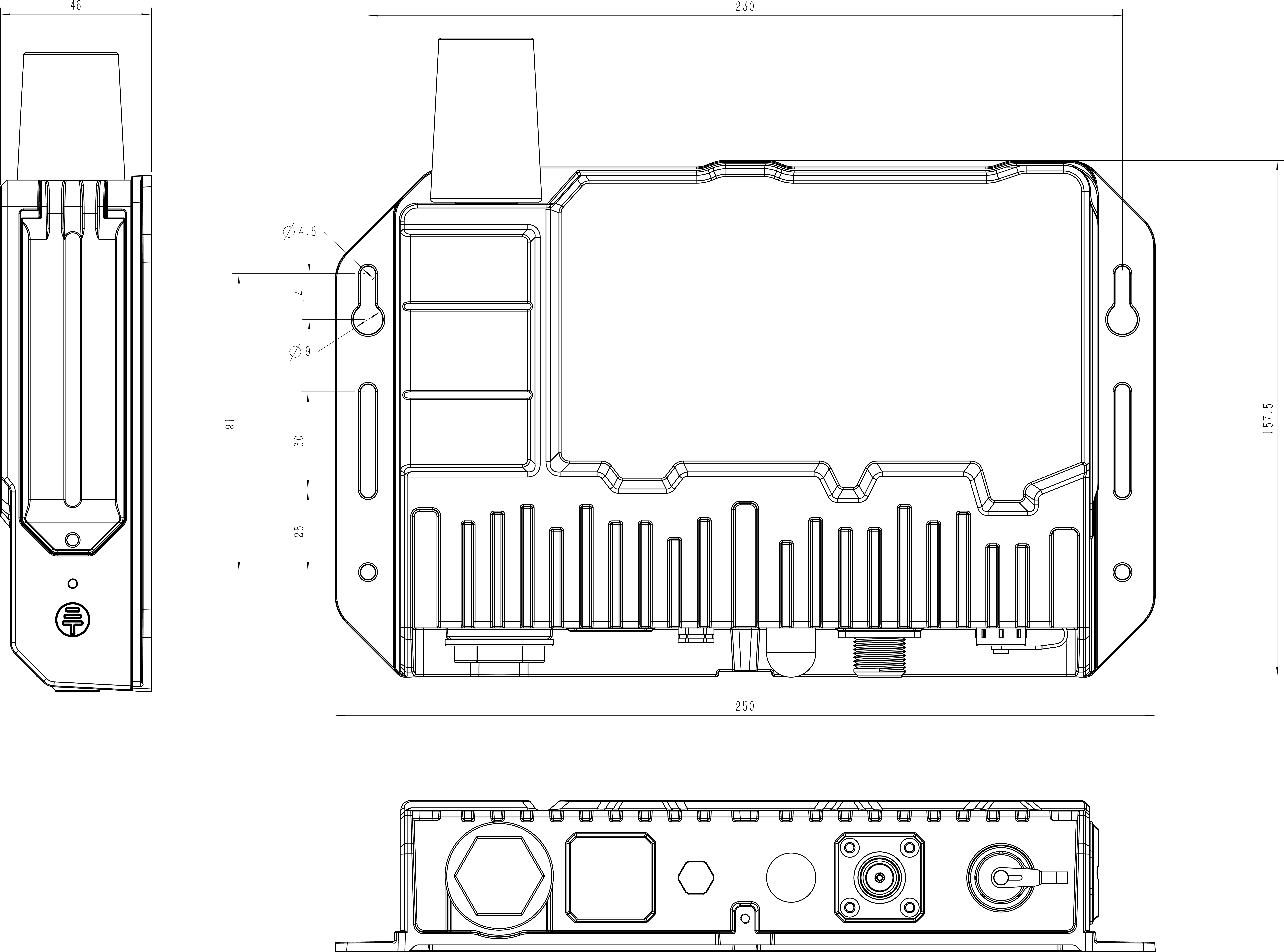
Device Dimensions
The following figure shows the device dimensions (unit:mm).