5.2.1 Configure LoRaWAN® Parameters
This section describes how to configure the device transmission parameters for the LoRaWAN® network. LoRaWAN® is enabled by default on this device.
Configure Join Type and Frequency
It is necessary to configure the join type and the frequency to establish communication with LoRaWAN® gateways.
- On the homepage of ToolBox, click Setting to enter the Setting page.
- On the top bar, select Network tab.
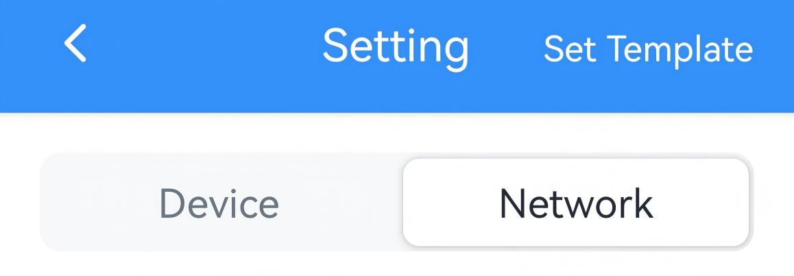
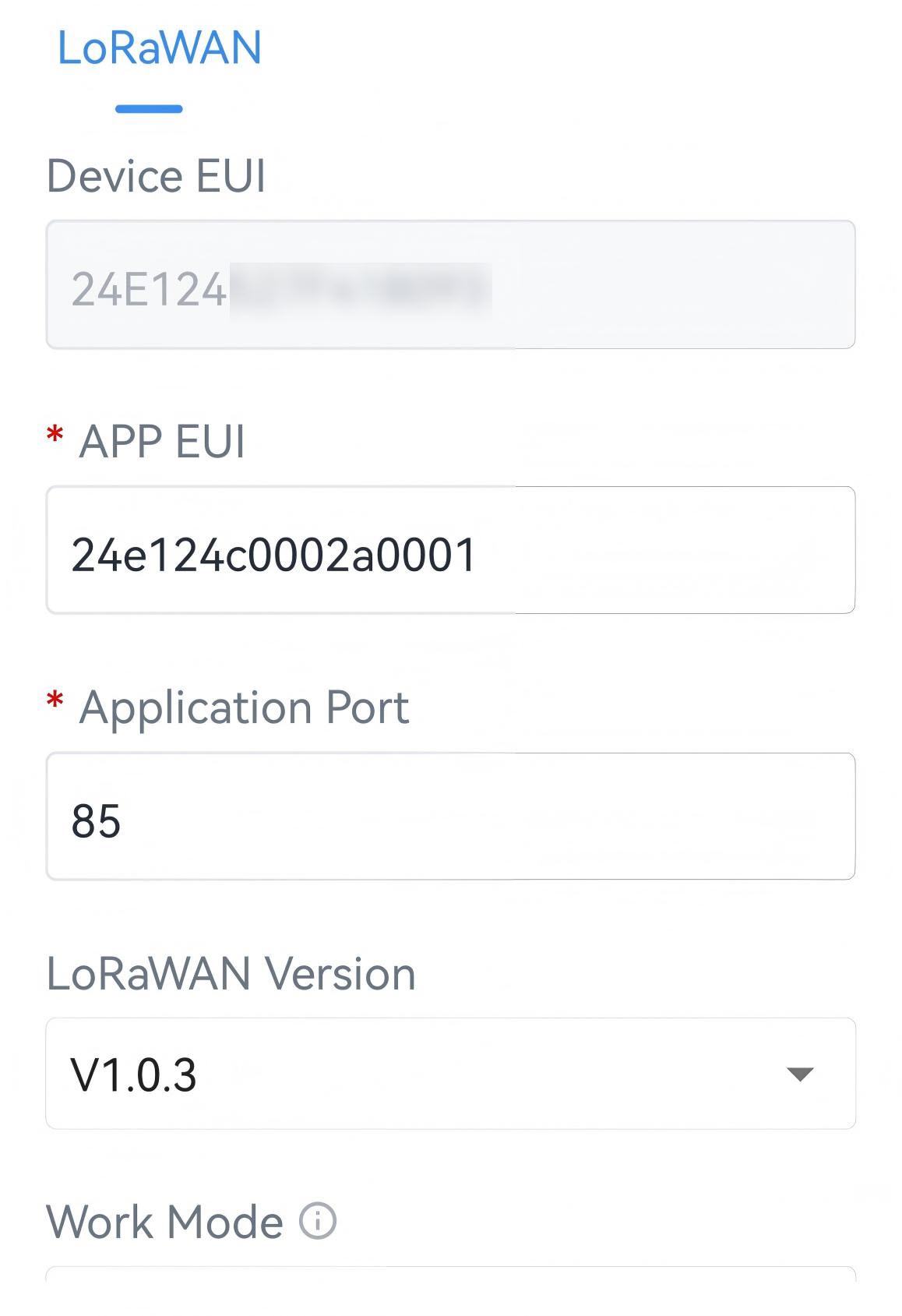
- Navigate to the LoRaWAN page The LoRaWAN
page is displayed, see the following figure.
- From the Join Type selection box, select OTAA or ABP as needed.Note: OTAA is required if you connect the device to the Milesight Development Platform.
-
Configure Join Type related parameters as needed. You can use default values unless otherwise specified.
- If OTAA is selected, configure Application Key and
Rejoin Mode as needed. For details, refer to the
following table.
Parameter Description Application Key Appkey for OTAA mode. Default: Device EUI + Device EUI (since Q4 of 2025).
Example: 24e124123456789024e1241234567890.
Default value of earlier devices: 5572404C696E6B4C6F52613230313823.
Tip: For device security, it is recommended to modify the default value or contact sales before purchase to use random keys.Rejoin Mode Rejoin mode for OTAA mode. Reporting interval≤35 minutes: The device sends a specific number of LinkCheckReq MAC packets at each reporting interval or every other reporting interval to verify connectivity.
Reporting interval > 35 minutes: The device sends a specific number of LinkCheckReq MAC packets at each reporting interval to validate connectivity. If there is no response, the device will re-join the network.
When Rejoin Mode is enabled, enter a number in the Set the number of detection signals sent text box. The actual sending number is the configured number +1.
- If ABP is selected, configure Network
Session Key, Application Session Key and
Device Address as needed. For details, refer to the
following table. Tip: For device security, it is recommended to modify the default values.
Parameter Description Network Session Key Nwkskey for ABP mode. Default: 5572404C696E6B4C6F52613230313823. Application Session Key Appskey for ABP mode. Default: 5572404C696E6B4C6F52613230313823. Device Address DevAddr for ABP mode. Default: 5th to 12th digits of SN.
- If OTAA is selected, configure Application Key and
Rejoin Mode as needed. For details, refer to the
following table.
-
Select a frequency from the Support Frequency selection box as needed. This must be the same as the frequency configured on the gateway's web GUI.
- If the Supported Frequency is US915 or
AU915, enter the channel index(es) separated by
commas.
Examples:
1, 40: Enabling Channel 1 and Channel 40
1-40: Enabling Channel 1 to Channel 40
1-40, 60: Enabling Channel 1 to Channel 40 and Channel 60
All: Enabling all channels
Null: All channels are disabledTip: Set the Channel Index to 8-15 when connecting to a Milesight LoRaWAN® gateway with default settings. - If the Supported Frequency is AS923, select a channel plan and enable the frequencies as needed.
- If the Supported Frequency is any option other than those listed above, enable the frequencies as needed.
- If the Supported Frequency is US915 or
AU915, enter the channel index(es) separated by
commas.
- Click Write in the lower right corner, and
put the NFC detection area of the phone close to the NFC antenna of device.
If the configuration succeeds, the following page is displayed.

Configure Other LoRaWAN® Parameters
Configure by ToolBox
- On the homepage of ToolBox, click Setting to enter the Setting page.
- On the top bar, select Network tab.
- Navigate to the LoRaWAN page The LoRaWAN
page is displayed, see the following figure.
-
Configure the following parameter as needed. You can use default values unless otherwise specified. For a description of the parameters, refer to the following table.
Parameter Description Device EUI Unique ID of the device labelled on the device housing. Tip: For bulk deployments, contact sales to request the device EUI list.App EUI The default App EUI (join EUI) is 24E124C0002A0001. Application Port Port used for sending and receiving data. Default: 85. LoRaWAN® Version Options: V1.0.2, V1.0.3. Work Mode Fixed as Class C mode. Confirmed Mode If the device does not receive ACK packet from network server, it will resend data once. Join Type Refer to Configure Join Type and Supported Frequency. Supported Frequency Refer to Configure Join Type and Supported Frequency. ADR Mode Enables the network server to adjust the spreading factor, the bandwidth and the transmission power to optimize data rates, airtime and energy consumption in the network. Spreading Factor If ADR mode is disabled, the device sends uplink data using this spreading factor. A higher spreading factor increases transmission range but reduces data rate and increases power consumption. This parameter varies with Supported Frequency. Tx Power Defined by the LoRa Alliance. Specifies the strength of the radio signal transmitted by the device. RX2 Data Rate RX2 data rate to receive downlinks. RX2 Frequency RX2 frequency to receive downlinks. Unit: Hz Multicast Group Enable or disable multicast groups. For more details, see Configure Multicast Group. - Click Write in the lower right corner, and
put the NFC detection area of the phone close to the NFC antenna of device.
If the configuration succeeds, the following page is displayed.
Configure Multicast Group
The device supports setting up multiple multicast groups to receive multicast commands from the network server, allowing users to control devices in bulk.
Step 1. Enable Multicast Group on the Device
- On the homepage of ToolBox, click Setting to enter the Setting page.
- On the top bar, select Network tab.
- On the LoRaWAN page, ensure the Application Port of each device is the same.
- Enable a Multicast Group, and configure the following parameter as
needed. You can use default values unless otherwise specified. For a
description of the parameters, refer to the following table.
Parameter Description Multicast Address Unique 8-digit address to distinguish multicast groups. McNetSKey 32-digit key. Default values: - Multicast Group 1: 5572404C696E6B4C6F52613230313823
- Multicast Group 2: 5572404C696E6B4C6F52613230313824
- Multicast Group 3: 5572404C696E6B4C6F52613230313825
- Multicast Group 4: 5572404C696E6B4C6F52613230313826McAppSKey 32-digit key. Default values: - Multicast Group 1: 5572404C696E6B4C6F52613230313823
- Multicast Group 2: 5572404C696E6B4C6F52613230313824
- Multicast Group 3: 5572404C696E6B4C6F52613230313825
- Multicast Group 4: 5572404C696E6B4C6F52613230313826 - (Optional) To enable another multicast group, follow the above step to configure the corresponding group.
- Click Write in the lower right corner, and
put the NFC detection area of the phone close to the NFC antenna of device.
If the configuration succeeds, the following page is displayed.
- JSON Command: multicast_group_config
- Raw Hex Command: Multicast Group Enable/Disable
The following steps use a Milesight gateway as an example. For other network servers, please refer to corresponding guides.
- Ensure the target devices are added to this gateway and have joined to the network.
- On the gateway web GUI, navigate to Network Server> Multicast
Groups page.
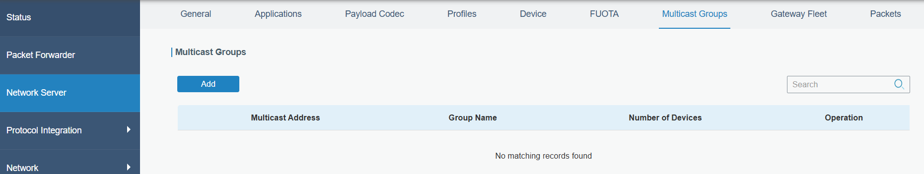
- Click Add to add a multicast group.
- Configure the multicast group parameters to match those configured on
ToolBox and select the devices that you need to control.
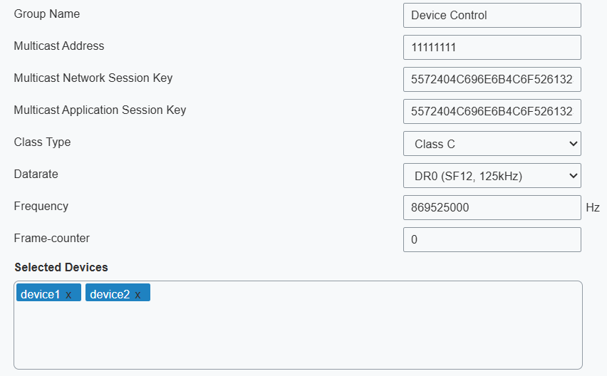
- Click Save to save this multicast group.
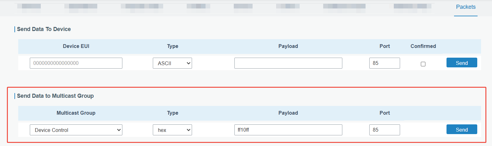
- Click Packets tab in the upper right corner.
- In the Send Data to Multicast Group section, select the multicast group from the Multicast Groups drop-down list and configure the downlink command parameters.
- Click Send. The network server broadcasts the command to all devices
in this multicast group.