Preparation before Installation
Installation Note
- It is recommended to inform people at the deployment site in advance that their images will be collected (through signage, user agreements, etc.) and obtain their consent before installation. Additionally, inform them that they may opt out if they do not consent to image collection.
- The device is sensitive to ambient light, so it's best to avoid placing it in areas where light conditions fluctuate significantly.
- To minimize false detections caused by reflections, avoid installing the device near mirror-like surfaces such as glass doors or mirrors. If unavoidable, position detection lines or areas away from these surfaces.
- When the device is installed at the door of the fan switch, the device needs to be installed on the opposite side of the door.
- For installation on door frames or above doorways, use the multifunctional bracket (available from Milesight or other sources). Adjust the bracket to ensure the device’s field of view remains clear of obstructions.
- Make sure there are no obstacles in the device's live view.
- For optimal depth detection performance, install the device in areas with rich environmental textures (e.g., patterned floors or walls). Avoid uniform surfaces such as plain white walls or solid-colored floors, as these may reduce accuracy.
- Keep the device parallel to the ground whenever possible. If unavoidable, ensure the tilt angle remains within 10 degrees.
Covered Detection Area
| Parameters | Explanation | Value |
|---|---|---|
| H | Installation height | VS125: 2.2 ~ 6 m VS125-LW: 1.9 ~ 3.5m |
| h | Target height | Example 1.7 m |
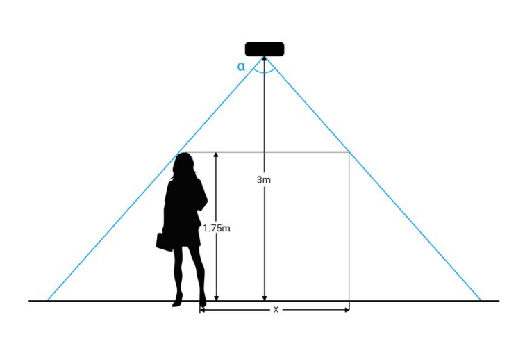
| α | Horizontal field of view angle | VS125: 101° VS125-LW: 130° |
| β | Vertical field of view angle | VS125: 70° VS125-LW: 117° |
| x | Length of detection range | 2 × tan(α/2) × (H-h+0.05) |
| y | Width of detection range | 2 × tan(β/2) × (H-h+0.05) |
The detection area depends on the device's field of view angle, installation height, and target height. The following figure uses the horizontal field of view angle, an installation height of 3 meters, and a target height of 1.75 meters as an example for illustration:
For example, if the pedestrians’ height is 1.75 m, the detection area corresponding to each installation height is as follows:
| Installation Height (m) | Detection Area (m) |
|---|---|
| 2.2 | 1.21 × 0.7 |
| 2.5 | 1.94 × 1.12 |
| 3.0 | 3.16 × 1.82 |
| 3.5 | 4.37 × 2.52 |
| 4.0 | 5.58 × 3.22 |
| 4.5 | 6.80 × 3.92 |
| 5.0 | 8.01 × 4.62 |
| 5.5 | 9.23 × 5.32 |
| 6.0 | 10.44 × 6.02 |
| Installation Height (m) | Detection Area (m) |
|---|---|
| 1.9 | 0.86 × 0.65 |
| 2.0 | 1.28 × 0.98 |
| 2.2 | 2.14 × 1.63 |
| 2.5 | 3.43 × 2.61 |
| 3.0 | 5.57 × 4.24 |
| 3.5 | 7.71 × 5.87 |