8.6.1.5 Traffic Detection
For Milesight, the Radar AI LPR Network Camera not only supports the embedded LPR algorithm, but also the deep learning algorithm based on the AI platform, which can achieve higher detection accuracy and richer intelligent functions.
Milesight Radar AI LPR camera is a truly all-in-one integrated camera. The radar module is directly integrated in the camera, making installation more convenient.
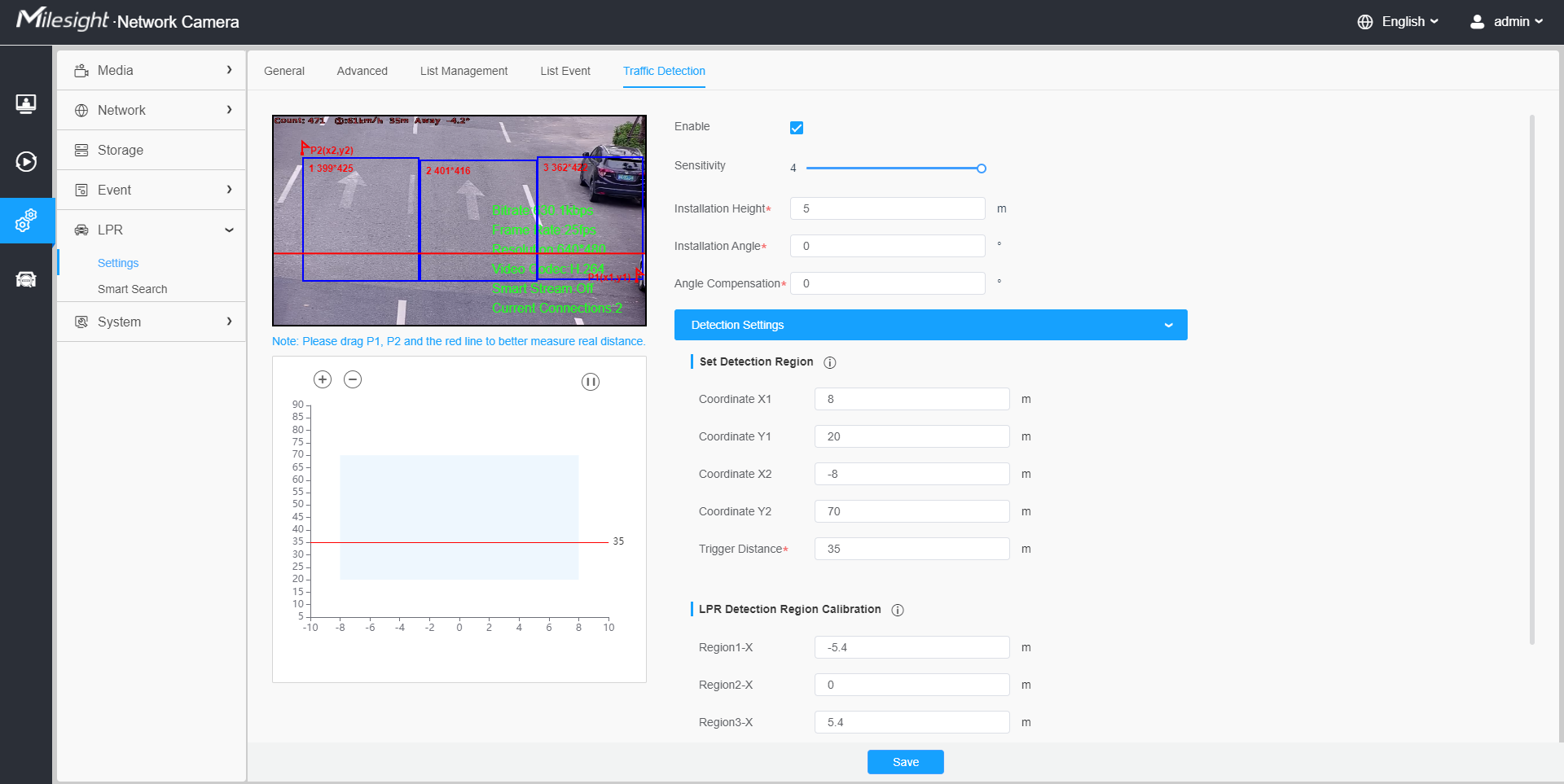
In this page, you can configure the Traffic Detection of Radar model.
- Make sure your camera model is Milesight Radar AI LPR Cameras.
- For more details, please refer to https://milesight.freshdesk.com/a/solutions/articles/69000797257.
Step1: Enable the traffic detection.
| Parameters | Function Introduction |
|---|---|
| Installation Height | Please fill in the installation height according to the actual installation height of the camera. |
| Installation Angle | Please fill in the installation height according to the actual installation angle between the camera's field of view and the horizontal. |
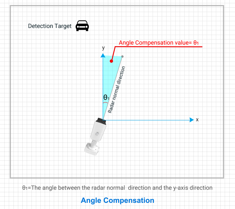
| Angle Compensation |
Support angle compensation range: -30°~30°, default 0°. Angle compensation is mainly used as horizontal angle compensation, such as the radar cannot be installed in the middle of the road, in order to detect data more accurate, the angle between the installation position and the road can be compensated and corrected. Angle Compensation value= θ1 θ1 is the angle between the radar normal direction and y-axis direction (Normally the y-axis is parallel to the road direction)
Note: The compensation angle value needs to be confirmed as positive
or negative, the angle between the camera's left rotation and
the y axis is defined as a positive angle, otherwise it is
defined as a negative angle.
|

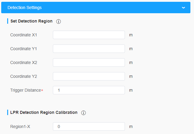
[Detection Settings]
Step2: Set Detection Region. Configure the radar detection area on the basis of the successful saving of the LPR detection area settings.
| Parameters | Function Introduction |
|---|---|
|
Set Detection Region |
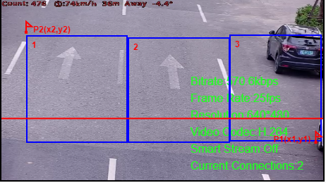
As shown in the figure below, there are two coordinate points. Points P1 and P2 are used to facilitate the user's spatial positioning.
The Radar detection area is a rectangle with diagonal lines in the two coordinate points; 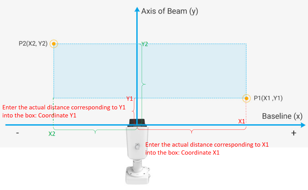 Please measure the actual position of the plane coordinates of the two vertices, taking the radar position as the zero position (0,0). Then fill in the parameter input boxes for the following two vertices: Coordinate X1/Y1: X/Y axis parameter of P1 coordinates.Coordinate X2/Y2: X/Y axis parameter of P2 coordinates. Trigger Distance: As shown in the radar configuration page in the figure below, there will be a red line in the preview box of the configuration page. The red line is the position that can be adjusted up and down, and the Trigger Distance is the horizontal distance from the red line to the radar. To ensure relative accuracy, users need to fill in after actual measurement. The LPR detection triggers the start of recognition through this distance, which promotes a better match between the LPR data and the radar data. 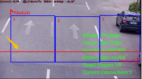 |
|
LPR Detection Region Calibration |
To match LPR data, please configure LPR detection region calibration after radar detection. The calibration of the LPR detection area is mainly to match the space coordinates. The number of this configuration item shows the corresponding number according to the number of the LPR detection area. The data filled in is based on the corresponding trajectory map on the right when the target vehicle enters the area to find the target and fill in the X value shown above. To match LPR data, please configure LPR detection region calibration after radar detection. For example, after you have drawn 3 detection areas, you can find the coordinate information corresponding to the targets in the detection area from the radar coordinates. You only need to fill in this coordinate information;
|

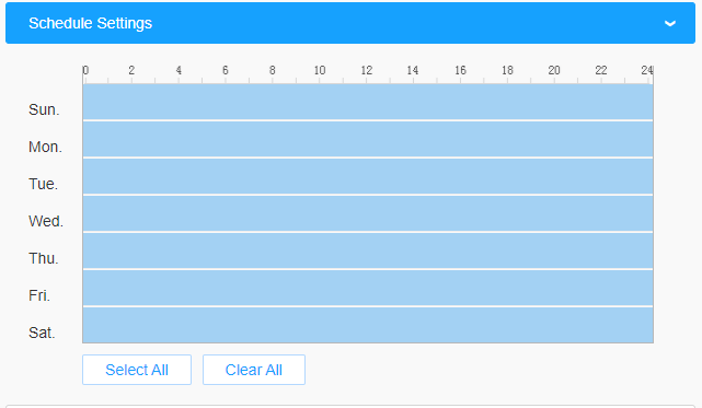
[Schedule Settings]
Step4: Schedule Settings. Set the effective time of traffic detection.
[Traffic Information]
Step5: Traffic OSD Settings. Customers can choose the information that needs to be displayed in Live Video and the display format, such as color, size, etc.

| Parameters | Function Introduction |
|---|---|
| Show OSD | Users can choose the information they want to display in Live Video. |
| Font Size | The font size of the OSD display, the default size is Medium. |
| Font Color | The font color of the OSD display. |
| Counting Reset | Click the "Reset" button to manually reset the vehicle count. |
| Auto Reset |
It is used to automatically clear the vehicle count at regular intervals (Just reset the OSD count for Live Video). |
| Day | The day of Auto Reset. |
| Time | The time of Auto Reset. |
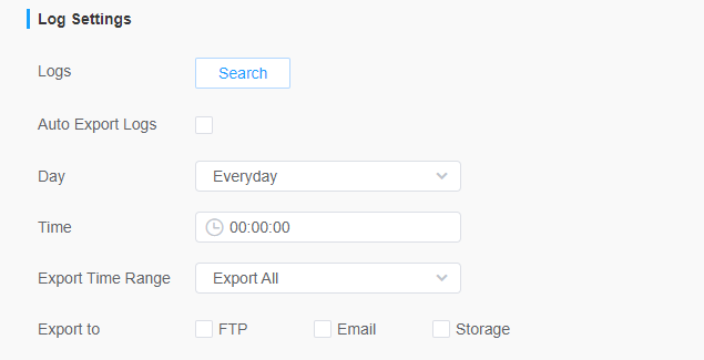
Step6: Log Settings. It allows users to search for various types of logs and support the log export function;
[Alarm Action]
Step7: Traffic Alarm Threshold. Used to set traffic alarm thresholds, such as maximum and minimum speed limits, and driving direction limits;
Step8: Set the alarm action. The OSD Blink here needs to be turned on after the OSD function. When an alarm is triggered, the OSD information will flash and alarm, and you can also set the duration of the OSD Blink Time, which supports 1~10s.
