Hardware Introduction
This chapter describes the hardware design of the device.
Hardware Overview
The following figure shows the main components of the device.
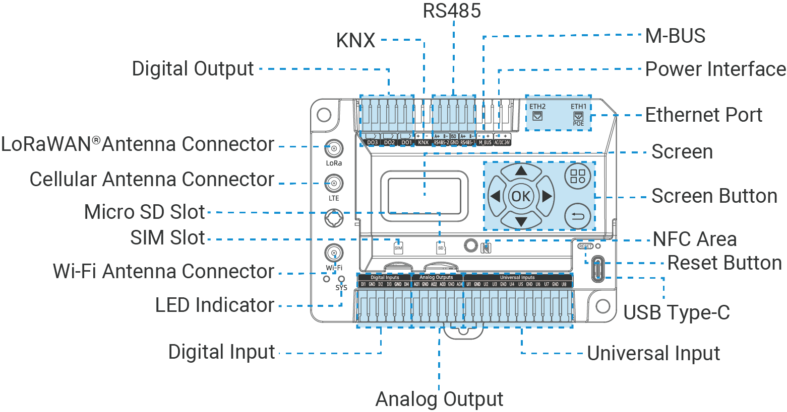
| Part | Description |
|---|---|
| LoRaWAN® Antenna Connector | Allows connection of external antennas to enhance wireless communication range and reliability. |
| Cellular Antenna Connector | |
| Wi-Fi Antenna Connector | |
| Micro SD Slot | Allows to insert a micro SD card to expand the storage. |
| SIM Slot | Allows to insert a SIM card to connect to the cellular network. |
| LED Indicator | See LED Patterns. |
| USB Type-C | Used for device console. |
| Reset Button | Allows to reset the device to factory defaults. For details see LED Patterns. |
| NFC Area | Allows addition of Milesight LoRaWAN® end devices. NFC is enabled by default. |
| Screen | Display the device's basic information, interface status, and operational status. |
| Screen Button | Used to check the device status and view the values of interfaces. |
| Ethernet Port | Allows connections of Ethernet end devices for data collection, or connection to an ISP for network access. ETH1 also supports the PoE PD feature, enabling it to receive power over Ethernet. |
| Power Interface | The interface for powering the device. For more details, refer to Wiring Diagrams. |
| M-BUS | The interfaces for connecting to terminal devices for data collection or control. For more details, refer to Wiring Diagrams. |
| RS485 | |
| KNX | |
| Digital Output | |
| Digital Input | |
| Analog Output | |
| Universal Input |
LED Patterns
| LED | Status | Description |
|---|---|---|
| NFC | Quickly Blinks | Reading and adding NFC device information |
| Rapid Blinks | Failed to add NFC device | |
| Static On 3s | NFC device added successfully | |
| SYS | Off | The power is switched off |
| Green Static On | The power is switched on and the system is working well | |
| Red Static On | The power is switched on and the system malfunctions | |
| On → Quickly Blinks | Factory Reset: Press and hold the reset button for more than 5 seconds | |
| Ethernet Port - Link Indicator (Yellow) | Off | Disconnected or connection failure |
| Static On | Connected | |
| Blinks | Transmitting data | |
| Ethernet Port - Rate Indicator (Green) | Off | Other modes |
| On | 1000 Mbps |
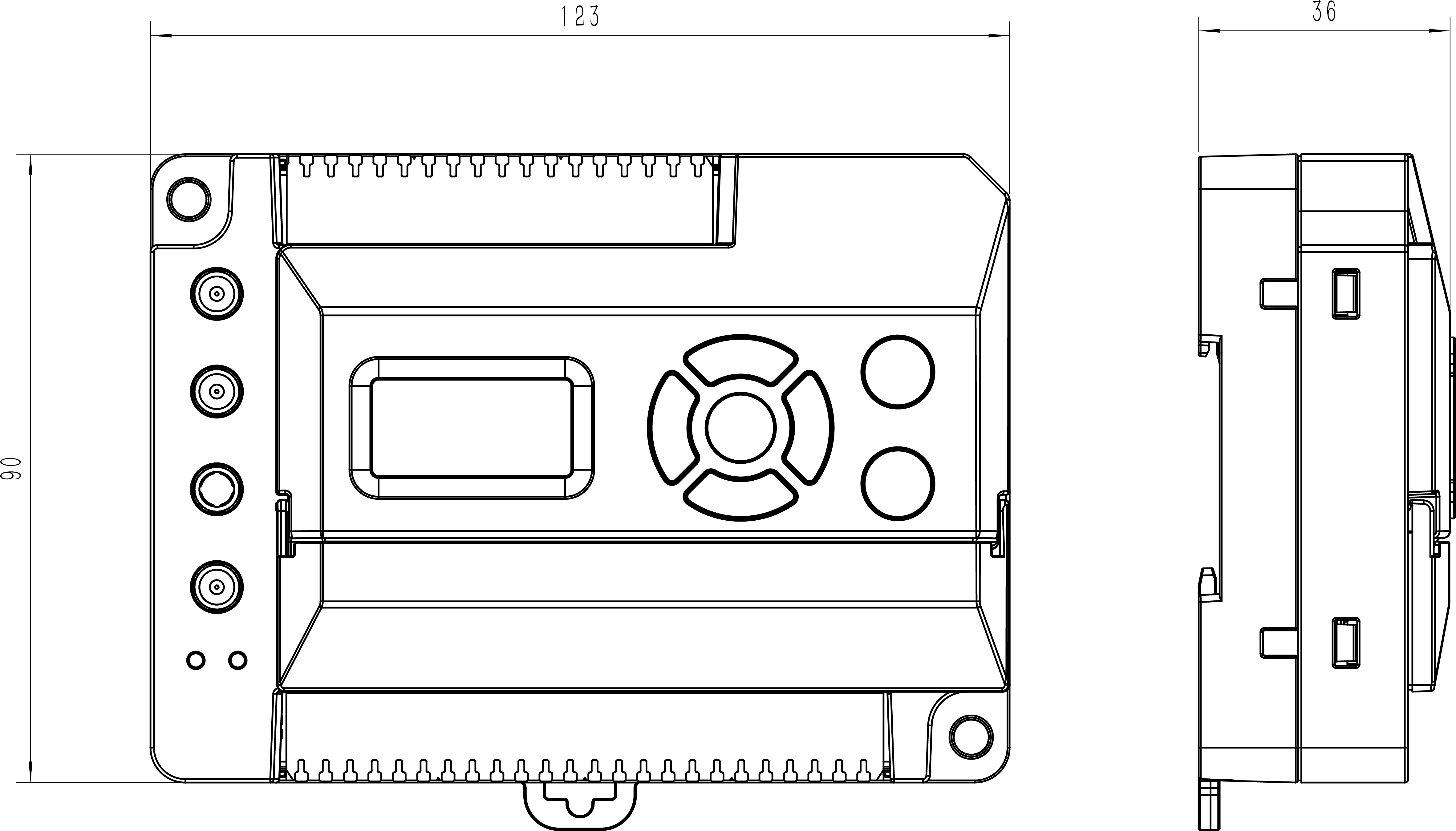
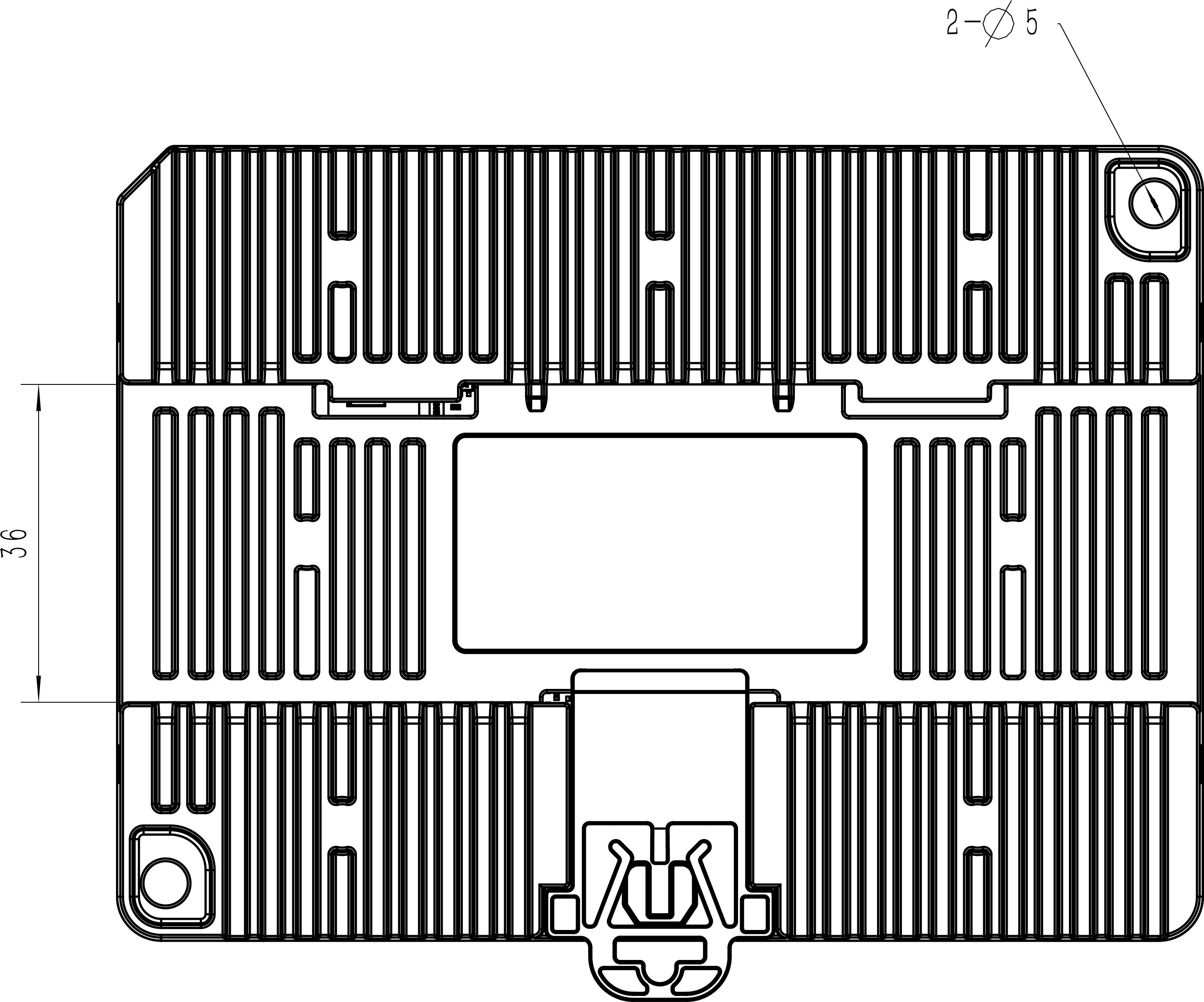
Device Dimensions
The following figure shows the device dimensions (unit:mm).
Screen Description
The screen displays multiple menu levels.
Main Menu
This menu displays the gateway model, SN, and network interface statuses.
| Interface | Icon | Description |
|---|---|---|
| Cellular |
|
Cellular is disabled |
|
|
Cellular module abnormal | |
|
|
No SIM card or SIM card error | |
|
|
PIN Error, PIN Required or PUK Required | |
|
|
SMSC Number Required, USSD Send Failed or Dial Number Required | |
|
|
Cellular is active, with 5
signal strength levels:
|
|
| WLAN |
|
WLAN is disabled |
|
|
WLAN AP is down | |
|
|
WLAN AP is up | |
|
|
WLAN Client is disconnected | |
|
|
WLAN Client is connected, with 5
signal strength levels:
|
|
| LoRaWAN® |
|
LoRaWAN® access network works well. |
|
|
LoRaWAN® access network works abnormally. | |
| ETH1 |
|
ETH1 is disabled |
|
|
ETH1 is disconnected or down | |
|
|
ETH1 is connected and up | |
| ETH2 |
|
ETH2 is disabled |
|
|
ETH2 is disconnected or down | |
|
|
ETH2 is connected and up |
Interface Status Menu
Press  button to navigate to the Interface Status
Menu. It has the following pages which can be switched by
button to navigate to the Interface Status
Menu. It has the following pages which can be switched by or
or  button:
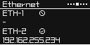
- Ethernet Status page: Displays the enabled status and IP address of
each Ethernet port.
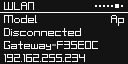
- WLAN Status page: Displays the work mode, connection status, SSID,
and IP address.
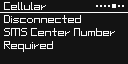
- Cellular Status page: Displays the cellular module status and network
connection status.
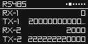
- RS485 Status page: Displays the number of TX and RX bytes for RS485
interface. The count will reset when switching to other pages.
- IO Status page: Displays the numbers of enabled interfaces. To check
the present values of each interface, click
 or
or  button to select the interface, then click
 button.
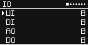
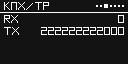
- KNX Status page: Displays the number of TX and RX bytes for the
KNX/TP interface. The count will reset when switching to other pages.
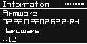
- Information page: Displays firmware version and hardware version of
the gateway.
Screen Buttons
| Button | Description |
|---|---|
|
|
Switches between the Main menu and the Interface Status menu. |
|
|
Returns to the previous menu level. |
|
|
Navigates to the next menu level. |
|
|
Switches the items in the IO Status page. |
|
|
|
|
|
Switches to the previous interface status page. |
|
|
Switches to the next interface status page. |