Wiring Diagrams
This chapter describes the wiring diagrams of interfaces.
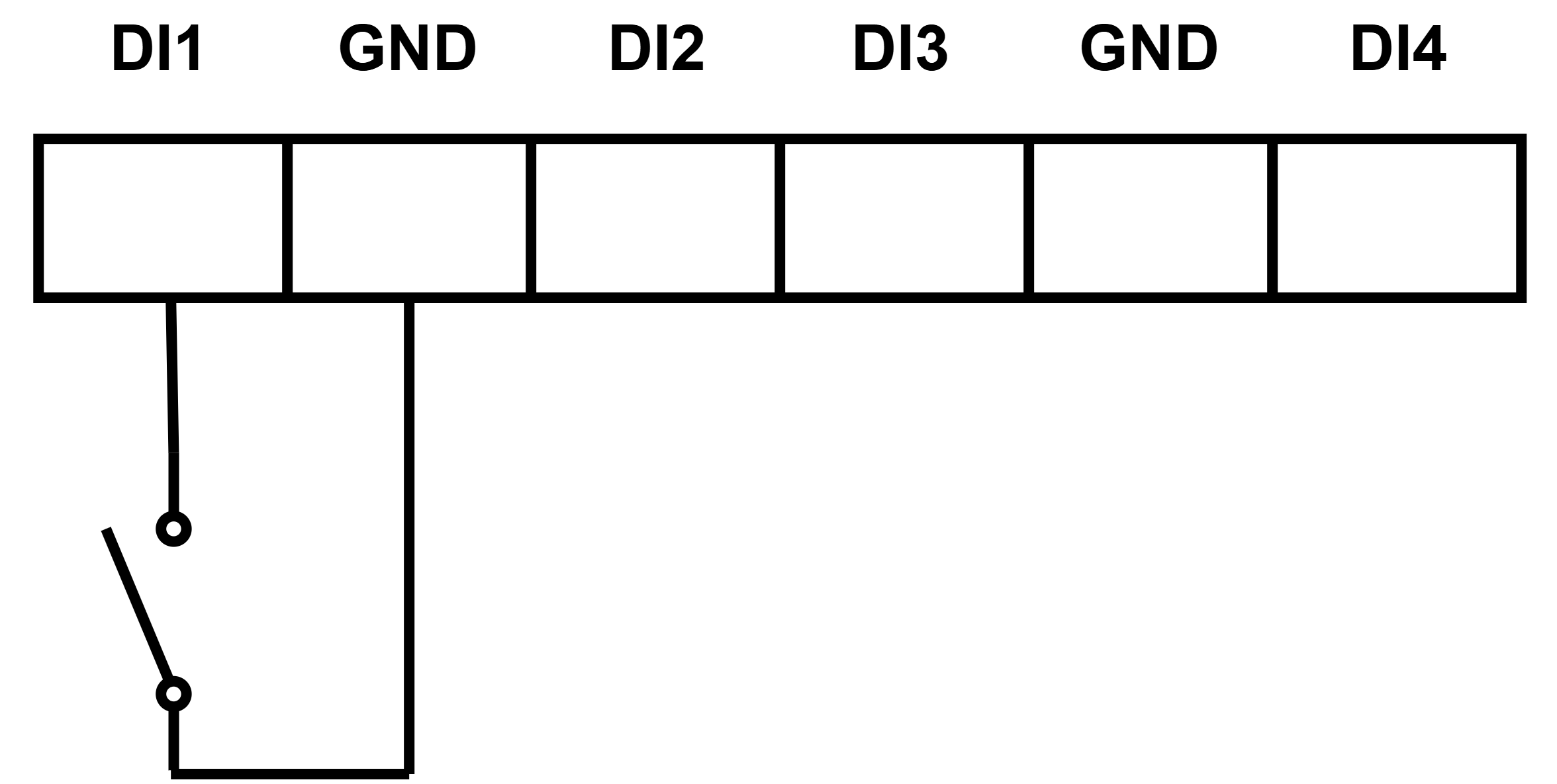
Digital Inputs
All digital inputs can function as standard dry contact inputs or pulse counters,
supporting pulse frequency counting up to 100 Hz. By default, two connected contacts
= low level, two disconnected contacts = high level.
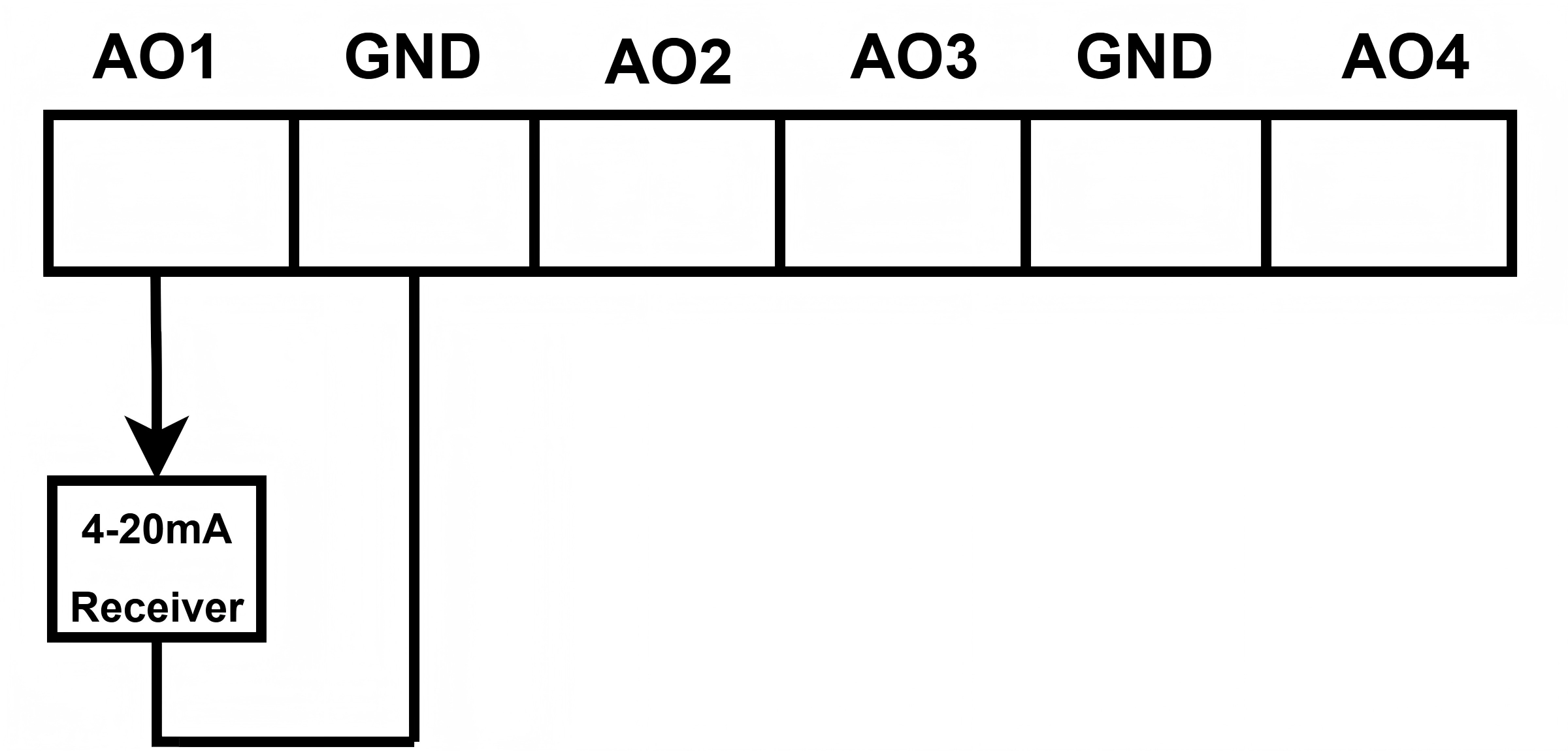
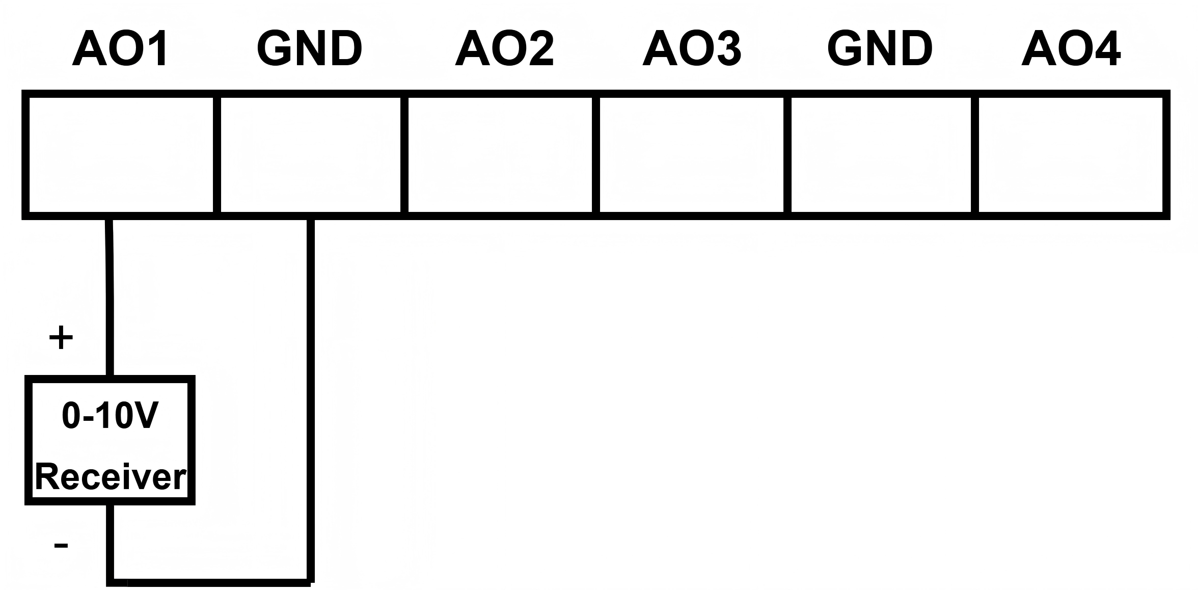
Analog Outputs
The analog outputs support switching output type between 4-20mA or 0-10V DC, with a
maximum load of up to 20mA.
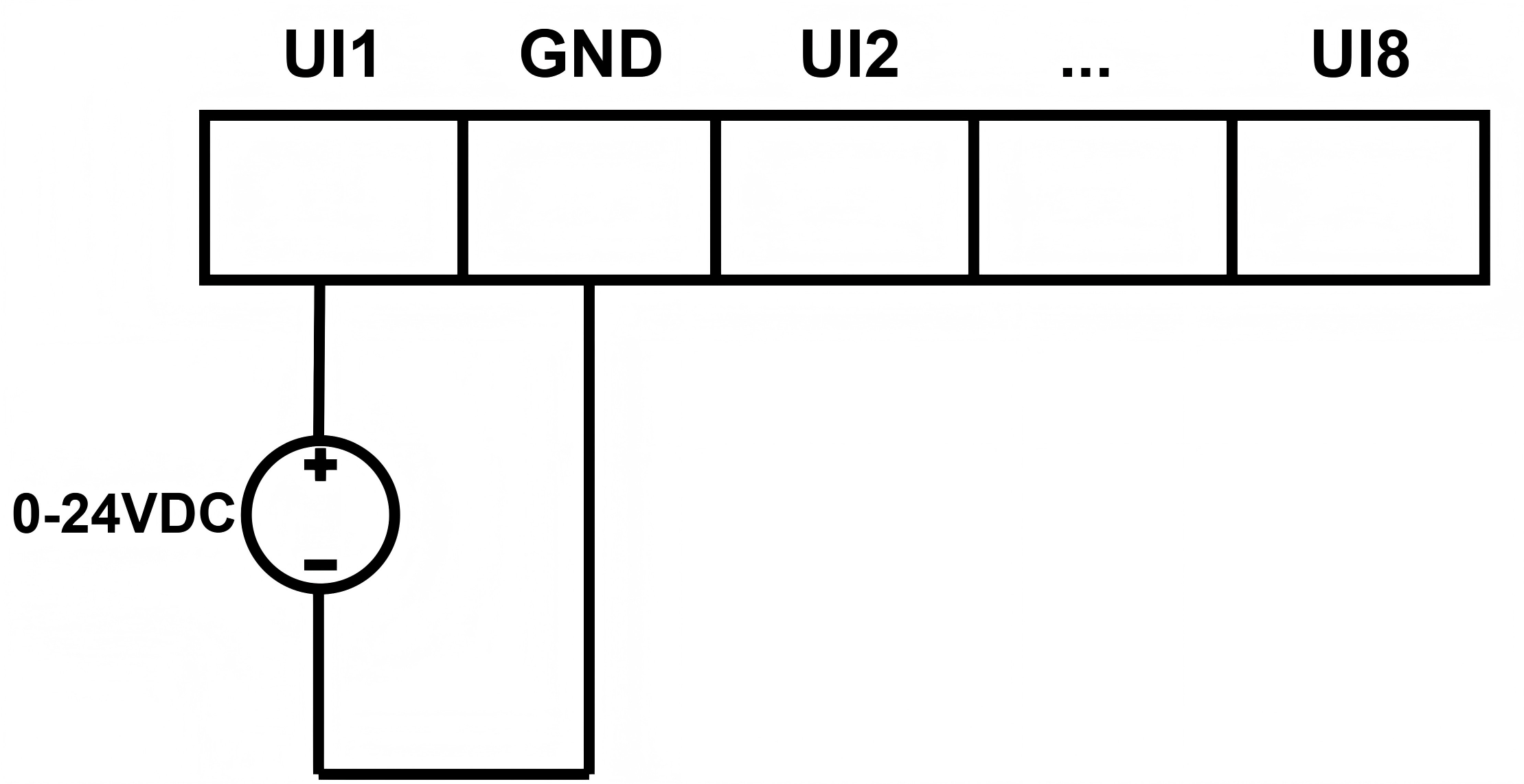
Universal Inputs
All universal inputs support switching among the following types of input signals via
software.
- Digital Input (Wet Contact)
- The universal inputs can work as standard digital inputs (wet contact
inputs). The low level ranges from 0-2V and the high level ranges from
2-24V (software-configurable).
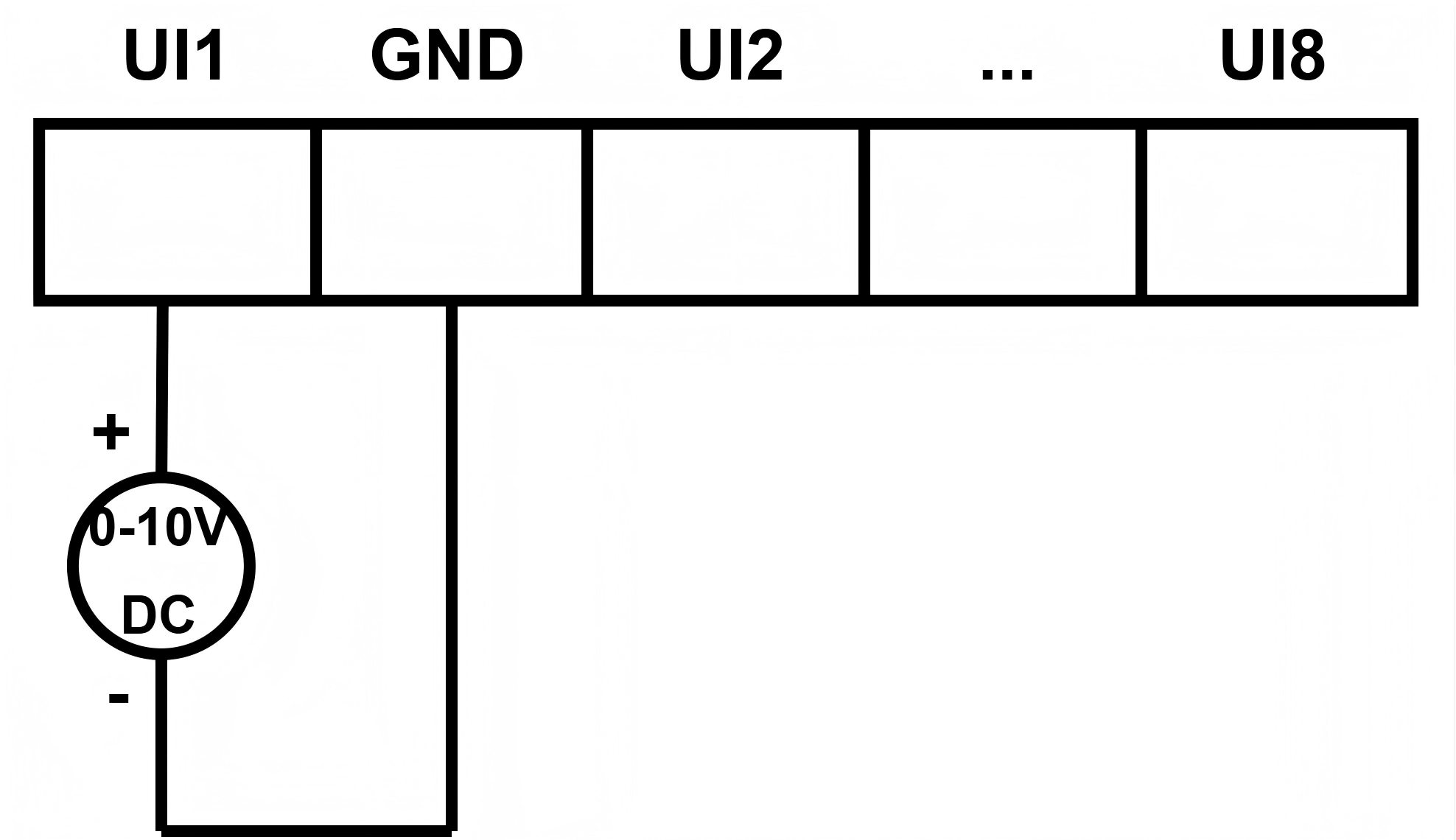
- Analog Input (0-10V)
- The universal inputs can work as standard analog inputs (0-10V DC).
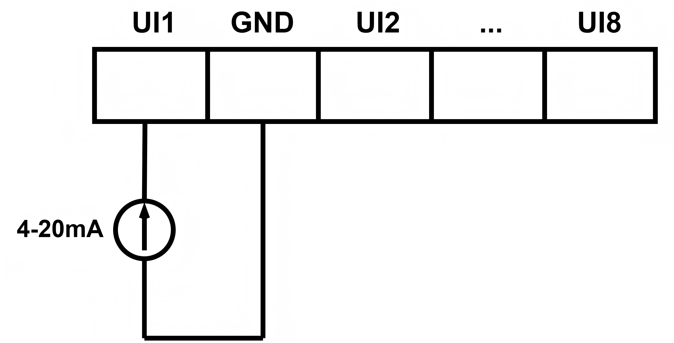
- Analog Input (4-20mA)
- The universal inputs can work as standard analog inputs (4-20 mA).
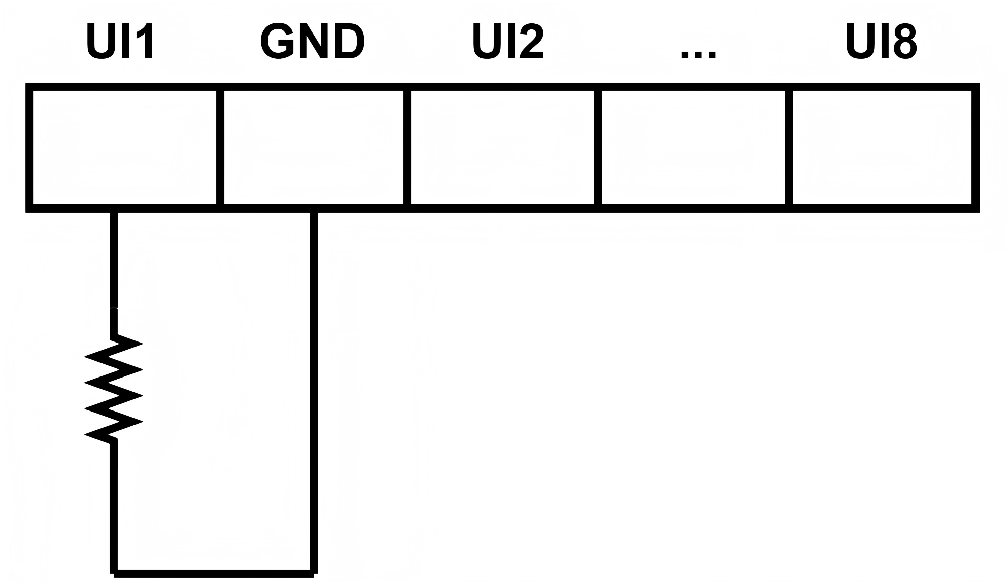
- Temperature/Resistance Input
- The universal inputs can work as temperature or resistance inputs to
connect the following types of sensors: PT1000, Ni1000, NTC 10k Type 2,
NTC 10k Type 3, NTC 20k, 1000 Ω, 2000Ω.
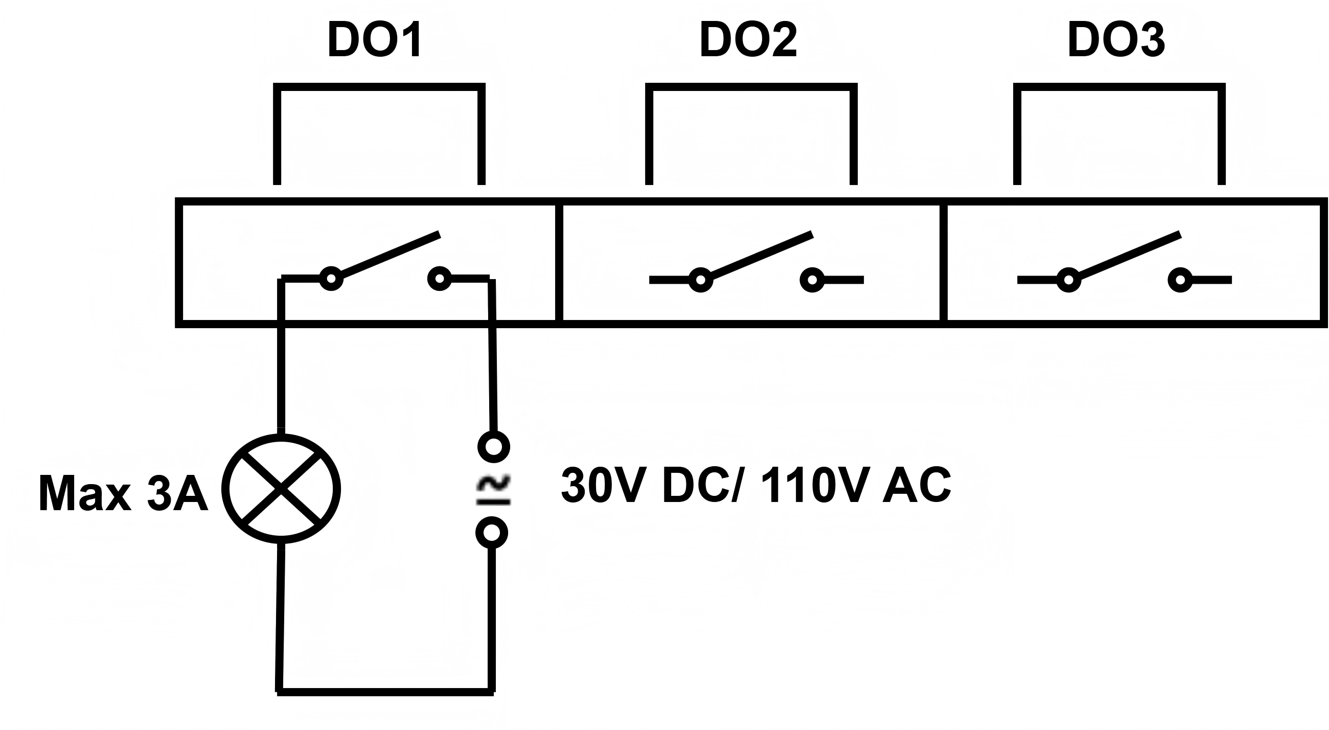
Digital Outputs
The relay outputs can connect to resistive loads up to 3A@110V AC or 3A@30V DC.
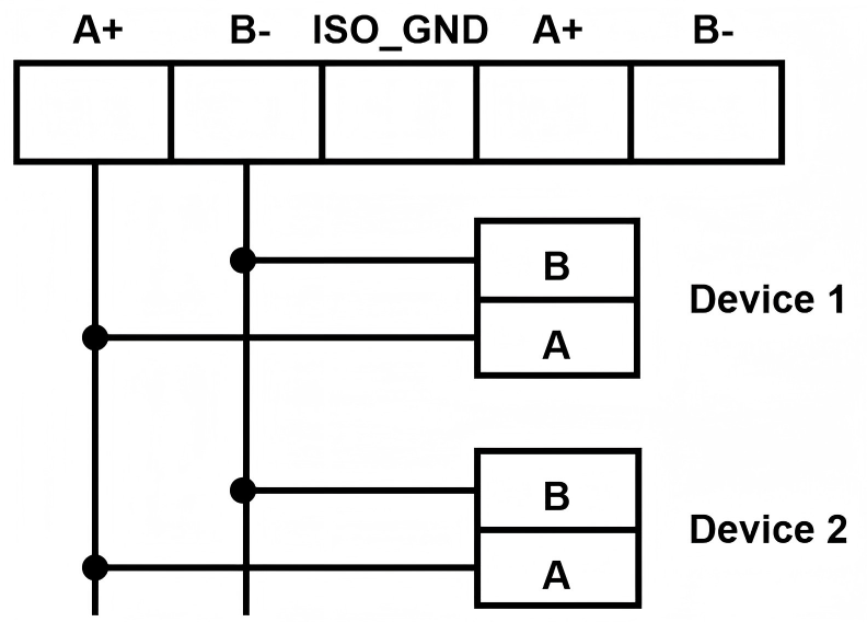
RS485
The RS485 interfaces support connecting to Modbus RTU or BACnet MS/TP devices.
Tip:
-
When connecting multiple devices to a single RS485 interface, a bus-type daisy-chain connection is recommended to ensure stable communication. A star topology should not be used for wiring.
- To add a 120Ω termination resistor across the A and B terminals of an RS485 interface, refer to DIP settings in the web GUI.
- ISO_GND is typically used when the RS485 cable is long or environmental interference is high.
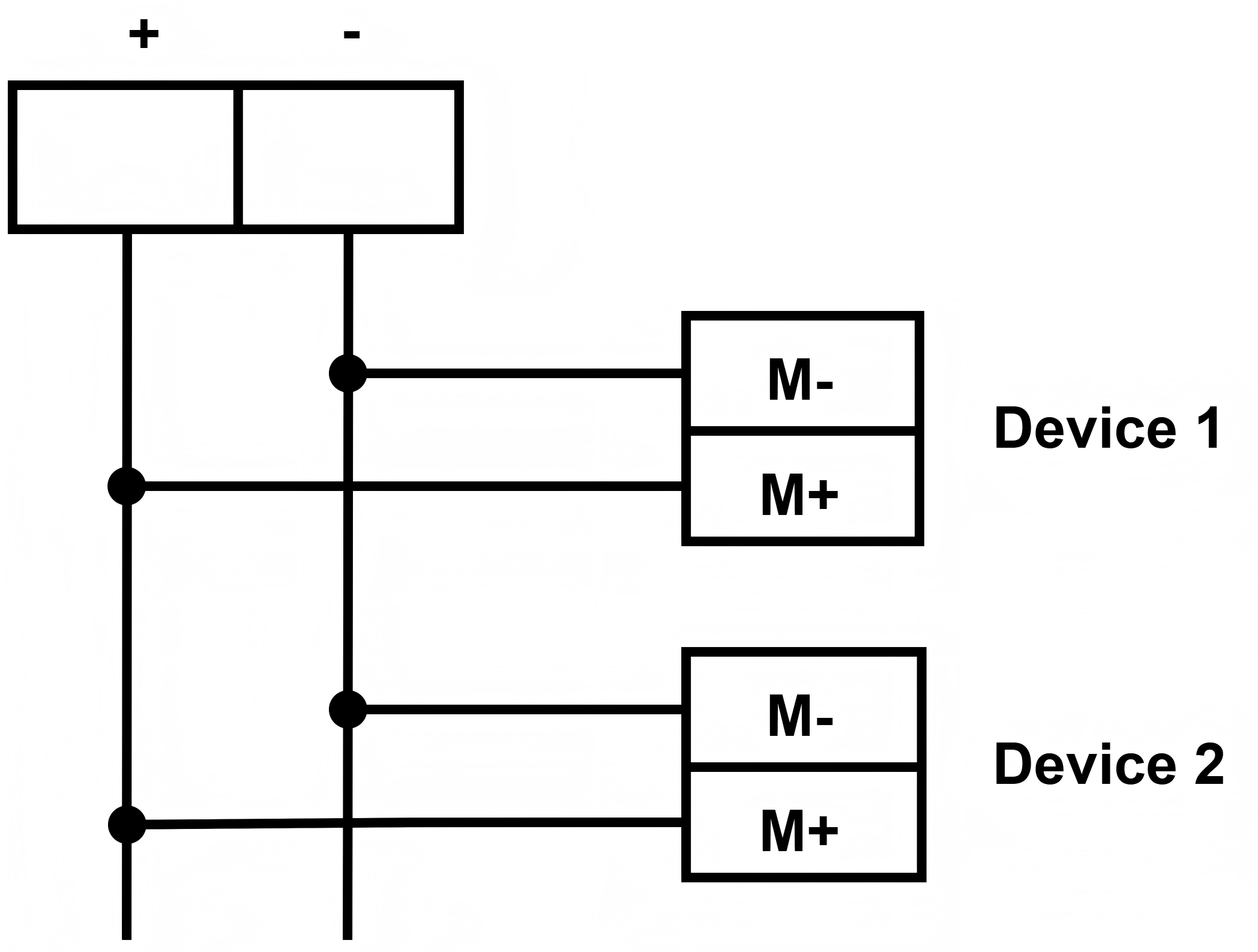
M-BUS (Under Development)
The M-BUS interface supports connecting to M-BUS devices.
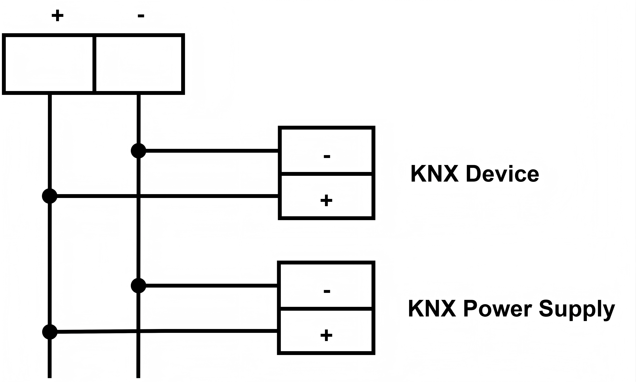
KNX
The KNX interface supports connecting KNX/TP1 devices and the KNX power supply.
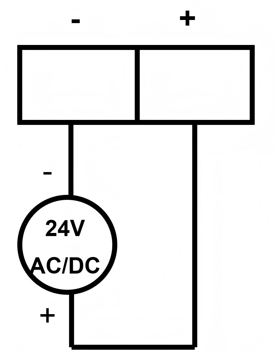
Power Supply (24V)
The power interface can supply 24V DC/AC power to the device.