Configure Installation Parameters
This section describes the settings related to the wirings.
Wiring Settings
The wiring settings are used to control the software state of the relays and define the supported functions.
- Navigate to Device > Installation.
- Enable the wire terminals that match the wirings during the installation.
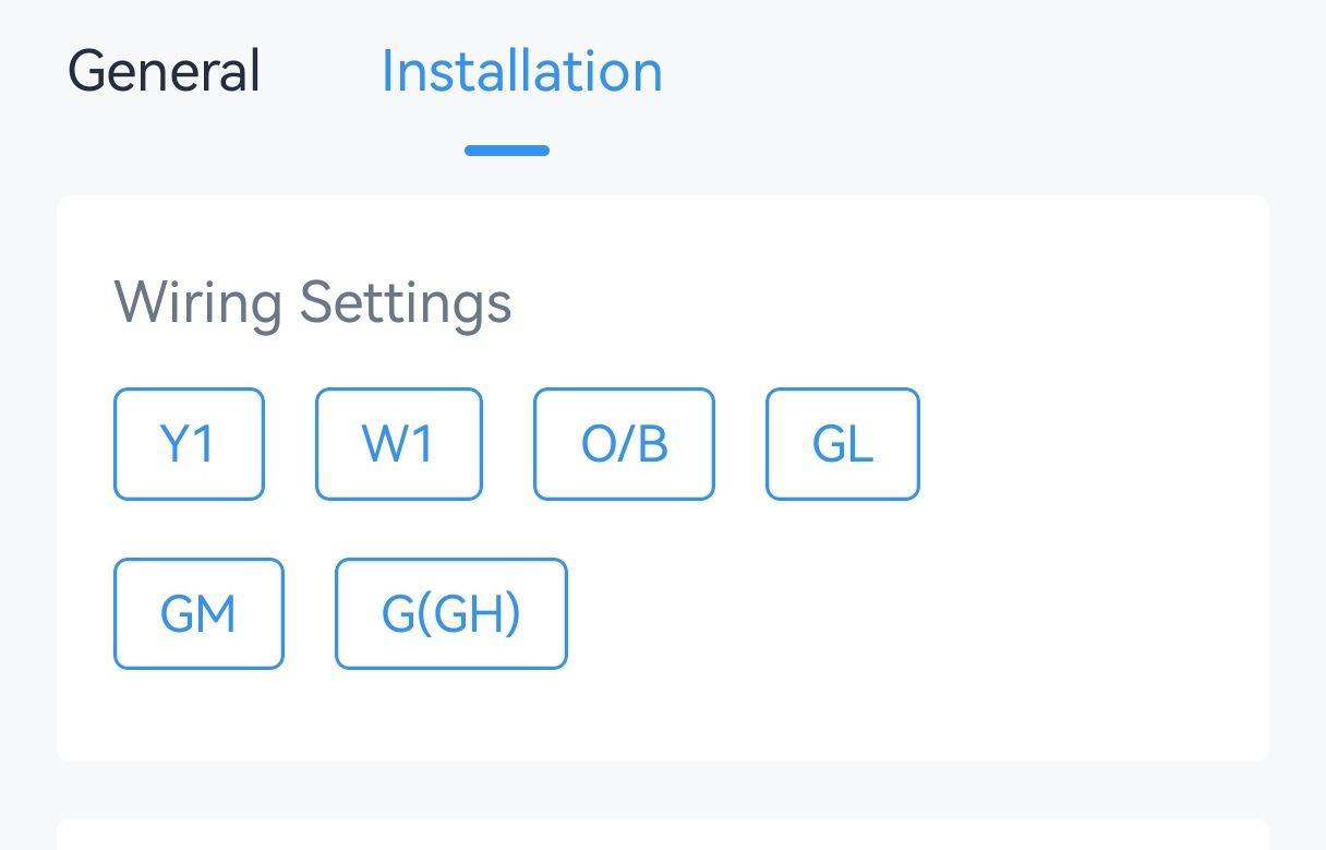
- Select the options according to the HVAC system.
Parameter Wire Description Reversing Valve O/B Switch the O/B mode of a heat pump or PTAC. Energize on Cool: O/B relay closed=cool (default)
Energize on Heat: O/B relay closed=heatFan Control during Heating W1+O/B+GH/GM/GL Select Thermostat or HVAC System. If HVAC System is selected, the fan will stop running when fan mode is Auto or Circulate. - Tap Write to apply the configuration.
- BACnet: See UC711 BACnet Object list, Installation Parameters.
- LoRaWAN Hex Command:
8E00,8E01,8E03. See UC711 Payload Protocol (HEX), Configure Installation Parameters.
Result
| Control Stage | Used Relay in Conventional System | Used Relay in Heat Pumps/PTAC |
|---|---|---|
| Stage-1 Cool | Y1 | Y1 |
| Stage-1 Heat | W1 | Y1 (+O/B) |
| Stage-2 Heat | / | W1 |
Compressor and Auxiliary Heat Linkage
| Heating Stage | 1-stage | 2-stage |
|---|---|---|
| Disable linkage | Y1+O/B | W1 |
| Enable linkage | Y1+O/B | Y1+O/B + W1 |
Prerequisites: Y1 + W1 + O/B are selected in Wiring settings.
- Navigate to Device > Installation.
- Enable Compressor and Auxiliary Heat Linkage.
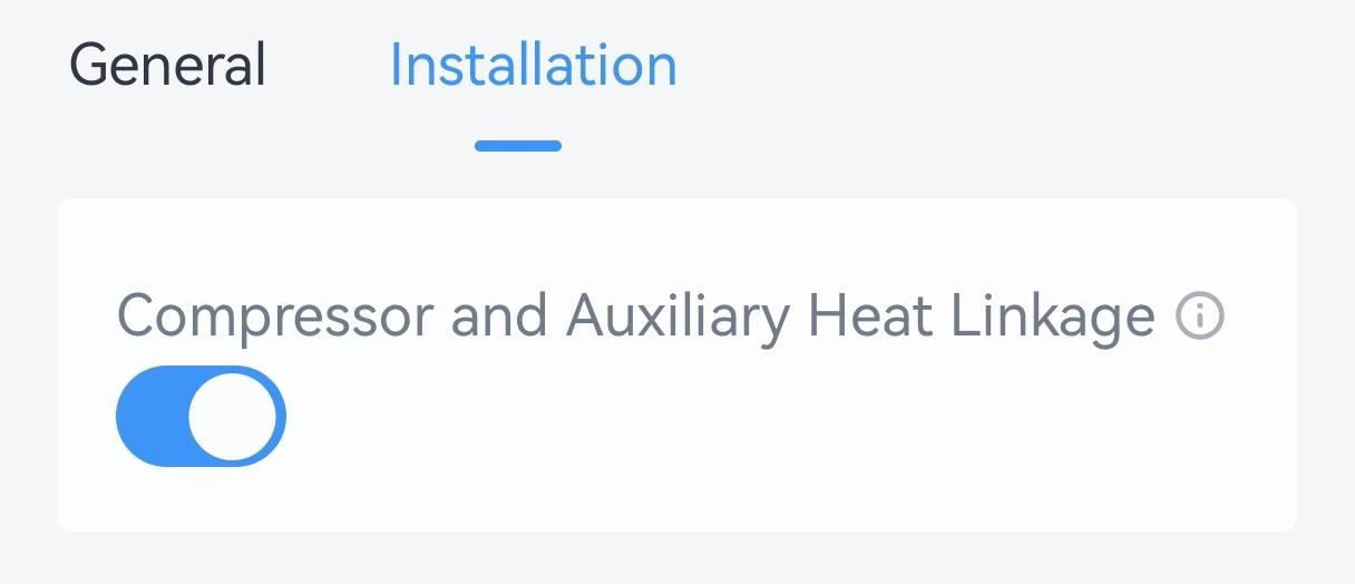
- Tap Write to apply the configuration.
- LoRaWAN Hex Command:
8E02. See UC711 Payload Protocol (HEX), Compressor and Auxiliary Heat Linkage.
System Protection
Prerequisites: Either Y1/W1/ GL/GM/GH is selected in Wiring Settings.
- Navigate to Device > Installation.
- Enable System Protection and configure the minimum running
duration.
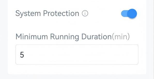
- Tap Write to apply the configuration.
- LoRaWAN Hex Command:
7400,7401. See UC711 Payload Protocol (HEX), System Protection.
Freeze Protection
The device supports switching to Heat system to avoid freezing when detecting that the ambient temperature is too low. This feature takes effect even when the system is off.
Prerequisites: Heat mode is supported. If Heat mode is not supported, the device will only send freeze protection trigger packet.
- Navigate to Device > Installation.
- Enable Freeze Protection and configure the protection
temperature.
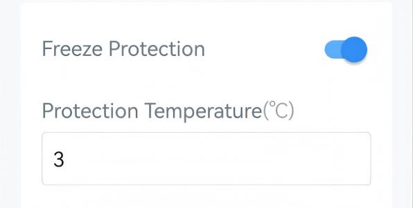
- Tap Write to apply the configuration.
- BACnet: See UC711 BACnet Object list, Installation Parameters.
- LoRaWAN Hex Command:
7100,7101. See UC711 Payload Protocol (HEX), Freeze Protection.
- When the device detects that the ambient temperature is lower than protection temperature, it sends a freeze protection trigger packet and starts heating.
-
When the device detects that the ambient temperature is higher than freeze protection temperature, it sends a freeze protection release packet and switch to the previous status.