Preparation before Installation
Covered Detection Area
| Parameters | Explanation | Value |
|---|---|---|
| H | Installation height | hmax+d+Δd≤ H ≤3.5 m |
| d | Minimum detection distance of device | 0.5 m |
| Δd | Distance measurement error of device | 0.035 m |
| hmax | Maximum pedestrian height | Example 1.8 m |
| h | Average pedestrian height | Example 1.7 m |
| α | ToF horizontal field of view angle | 98° |
| β | ToF vertical field of view angle | 80° |
| x | Length of detection range | 2 × tan(α/2) × (H-h) |
| y | Width of detection range | 2 × tan(β/2) × (H-h) |
- Example:
- When the maximum pedestrian height is 1.8 m, then the minimum installation height is 1.8+0.5+0.035=2.335 m.
The monitored area refers to the range visible to the device, which is displayed on the dashboard; the detection area, which is smaller, refers to the range within the monitored area where the device can detect changes in the number of people.
The detection area depends on the device's field of view angle, installation height, and target height. The following figure uses the horizontal field of view angle, an installation height of 3 meters, and a target height of 1.7 meters as an example for illustration:
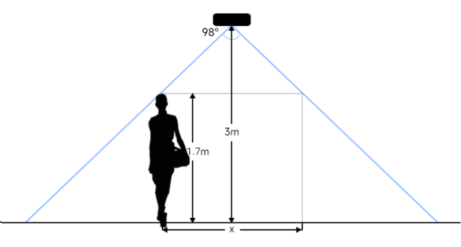
For example, if the Average height of pedestrians is 1.7 m, the detection area corresponding to each installation height is as follows:
| Installation Height (m) | Monitored Area (m) | Detection Area (m) |
|---|---|---|
| 2.5 | 5.75 × 4.20 | 1.84 × 1.34 |
| 2.6 | 5.98 × 4.36 | 2.07 × 1.51 |
| 2.7 | 6.21 × 4.53 | 2.30 × 1.68 |
| 2.8 | 6.44 × 4.70 | 2.53 × 1.85 |
| 2.9 | 6.67 × 4.87 | 2.76 × 2.01 |
| 3.0 | 6.90 × 5.03 | 2.99 × 2.18 |
| 3.1 | 7.13 × 5.20 | 3.22 × 2.35 |
| 3.2 | 7.36 × 5.37 | 3.45 × 2.52 |
| 3.3 | 7.59 × 5.54 | 3.68 × 2.69 |
| 3.4 | 7.82 × 5.71 | 3.91 × 2.85 |
| 3.5 | 8.05 × 5.87 | 4.14 × 3.02 |
Installation Position
- Avoid installing the device against the wall and ensure that the distance
between the device and the wall as follows:
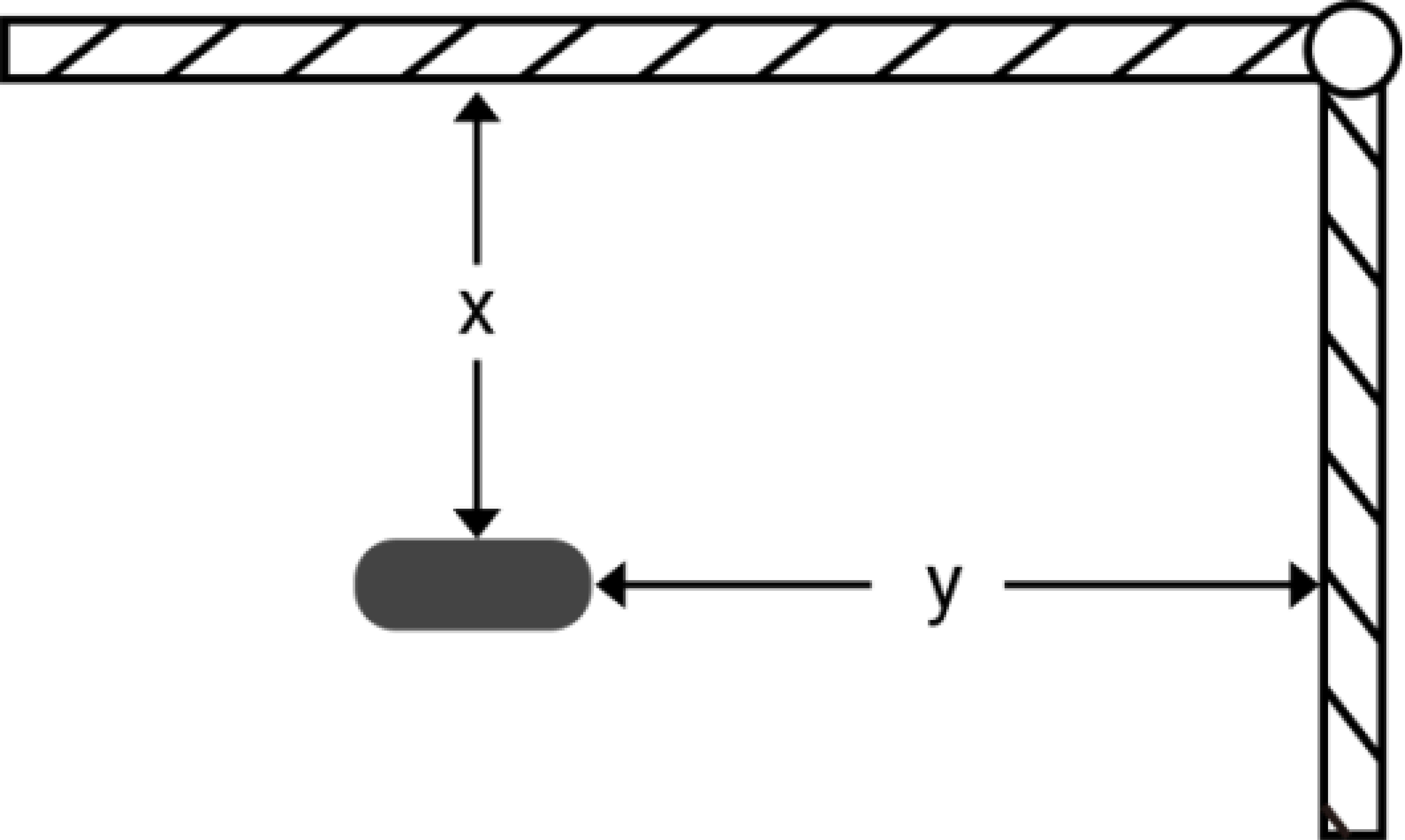
-
Condition Standard Environment The carpet/floor is Dark (need to set max noise filtering level) Normal imaging x>50cm, y>60cm x>50cm, y>75cm Normal counting x>50cm, y>50cm x>50cm, y>50cm
-
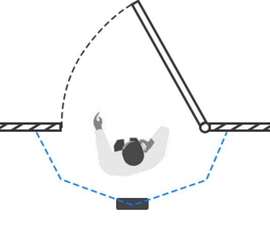
- When you install devices on the top of swinging doors, it is suggested to keep
the door normally open. If the door must be normally closed, please install the
device on the other side of the door to keep away from the door movement. And it
is suggested to keep away from the door with a distance of at least 30 cm.
- Ensure that there are no other objects blocking the ToF light within a 30 cm radius of the front of the device.
- Tilt installation should be avoided. Ensure that the front of the device and the ground plane are paralleled.
Environment Requirements
- Avoid 940nm light which may result in incorrect counting.
- Outdoor sunlight shining on the over channel will not have any effect, but the mirrored reflections that allow sunlight to shine on the ToF Sensor should be avoided.
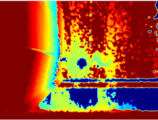
- Make sure there are no obstacles within the live view of device. Otherwise, the
device imaging may appear abnormally red or it will affect people counting. Set
the appropriate noise filtering level according to the actual image. The more
difficult it is to see the target, the higher the filter value should be.