Multi-Device Stitching
Overview
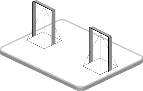
Multi-device stitching is mainly used to monitor a larger detection area than just the area covered by a single device. When using this feature, devices should be installed next to each other and ensure the detection areas are tangent or overlapping.
- Ensure the head of one person can be seen on both live views at the same
time.
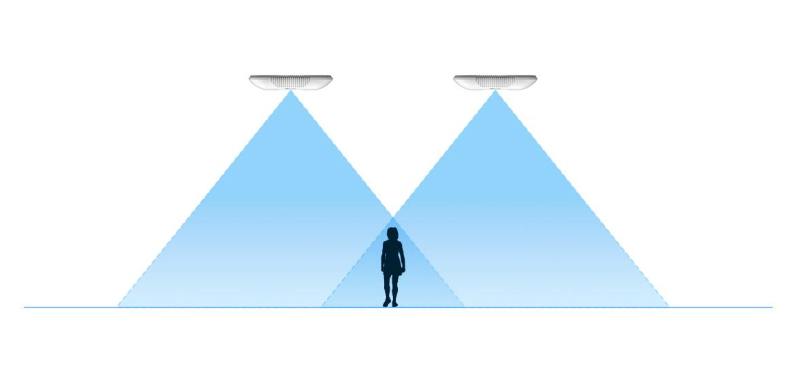
- The devices can also be installed without overlapping.
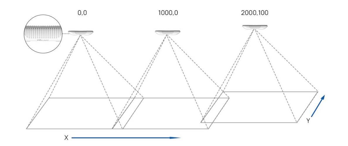
- Device positioning is done via X&Y coordinates. For example, the
installation direction of the master device is shown as below, the logo
needs to be facing the front. When the master device’s coordinate is (0, 0),
the coordinates of the node devices are all positive values.
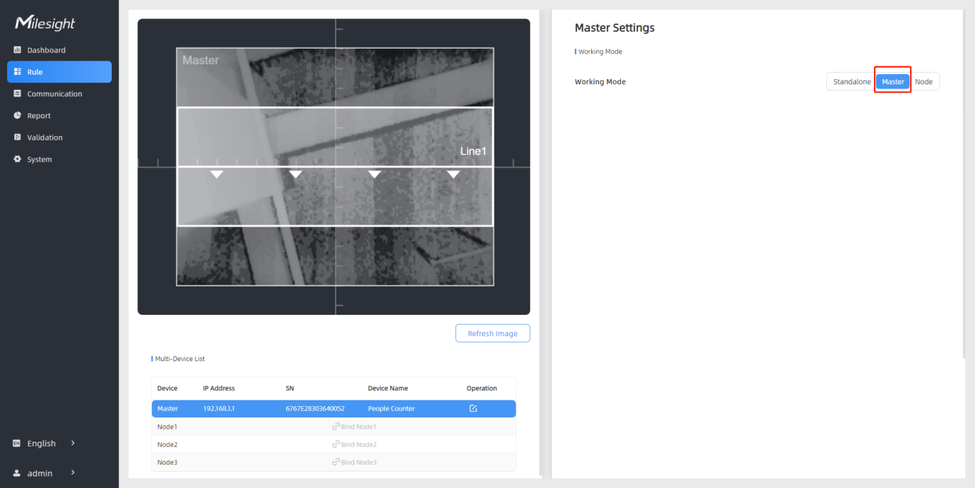
Before using this feature, set one device as Master Mode and other devices as Node Mode.
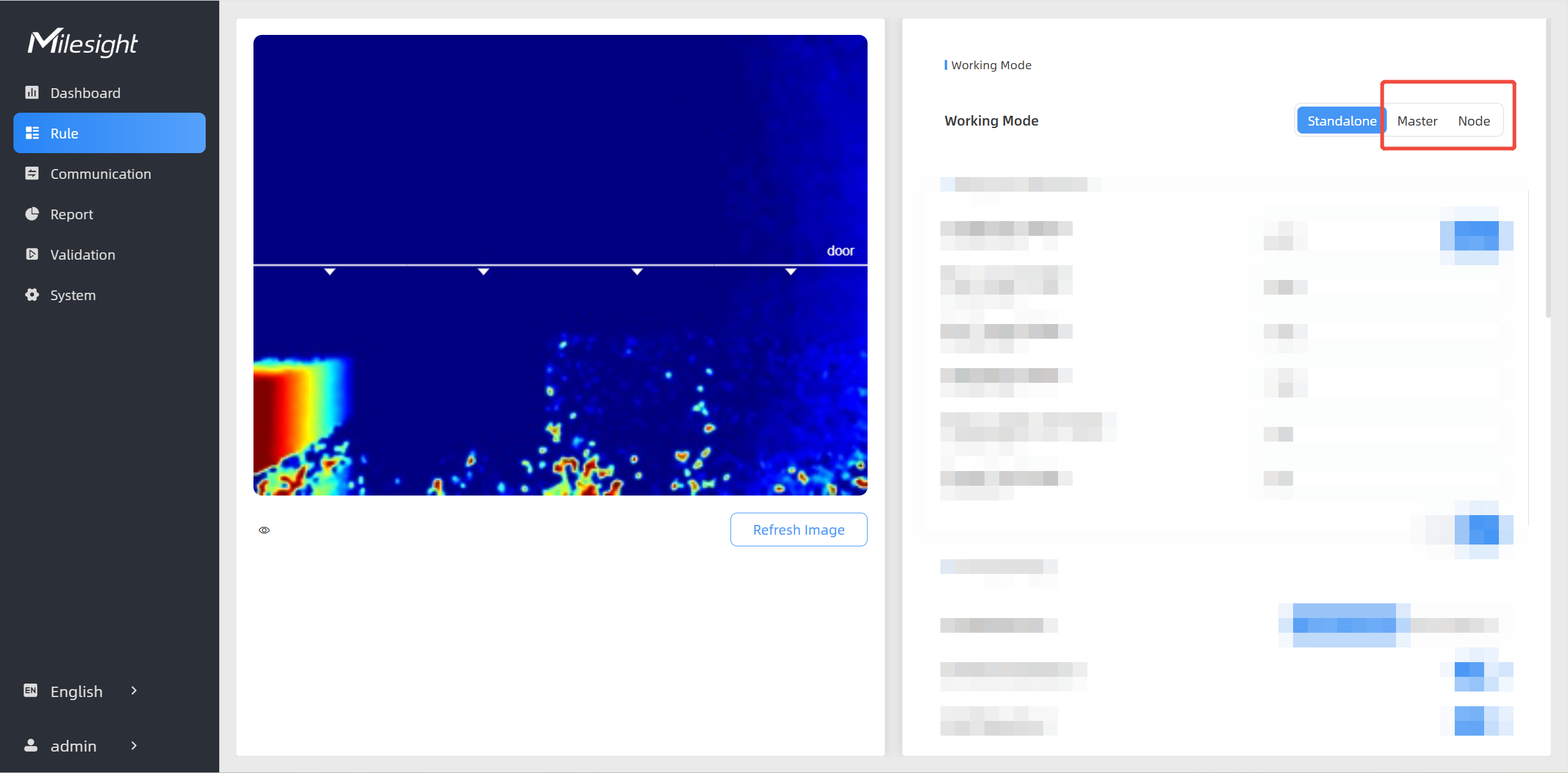
- Master Mode: Receive target tracks and view from the device, responsible for all counts, rule setting, data push and other functions.
- Node Mode: Only extends the view of the master device.
Multi-Stitching Compatible List
| Stitching | Master Device | Node Devices | Stitching Number |
|---|---|---|---|
| Support | VS135-P | VS135-P | 8 |
| VS135-P-High | VS135-P-High | ||
| VS135-L08EU | VS135-P, VS135-HL, VS135-LoRa, VS135-L08EU |
4 | |
| VS135-L08EU-High | VS135-P-High, VS135-HL-High, VS135-LoRa-High, VS135-L08EU-High |
||
| VS135-HL | VS135-P,
VS135-L08EU, VS135-LoRa, VS135-HL |
||
| VS135-HL-High | VS135-P-High, VS135-L08EU-High, VS135-LoRa-High, VS135-HL-High |
||
| VS135-LoRa | VS135-P,
VS135-L08EU, VS135-HL, VS135-LoRa |
||
| VS135-LoRa-High | VS135-P-High, VS135-L08EU-High, VS135-HL-High, VS135-LoRa-High |
||
| Not Support | VS135-P | VS135-LoRa, VS135-L08EU, VS135-HL |
/ |
| VS135-P-High | VS135-LoRa-High, VS135-L08EU-High, VS135-HL-High |
||
| VS135 standard versions | VS135 high ceiling mount versions | ||
| VS135 high ceiling mount versions | VS135 standard versions | ||
| VS133-P | VS135-P | ||
| VS135-P | VS133-P |
Node Device Setting
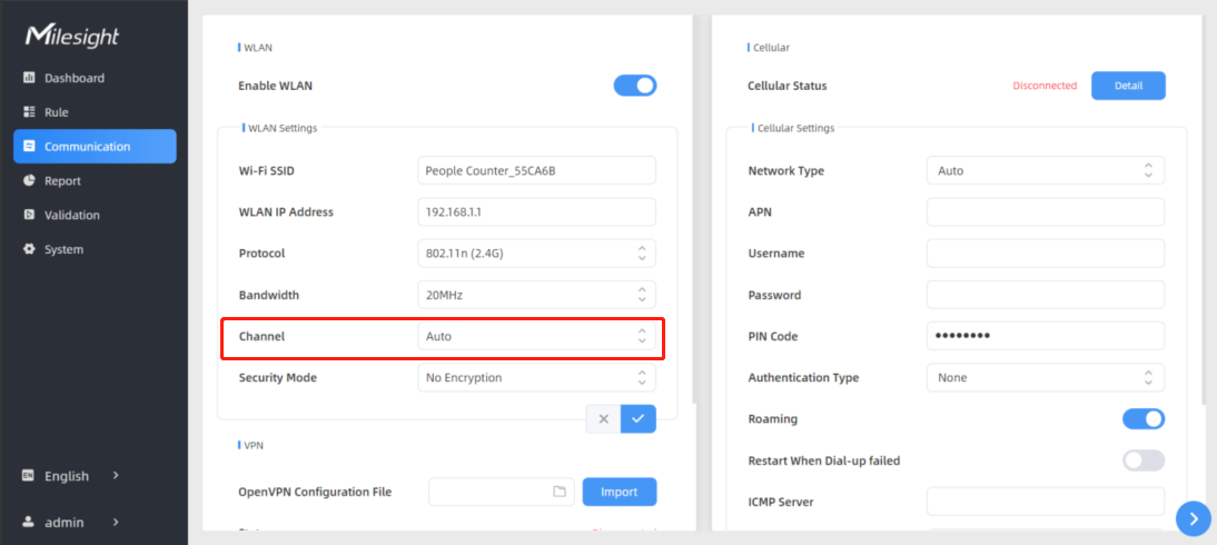
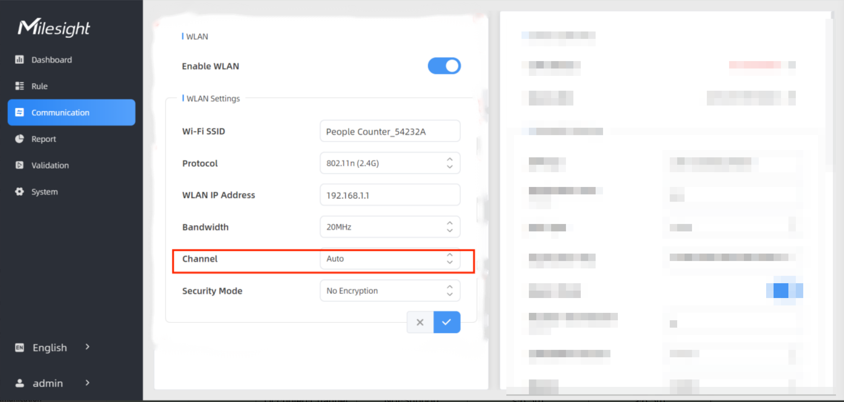
Step 1: change the WLAN IP Address of node devices to different subnets from master device’s WLAN IP address. If the master device is a PoE version device, skip this step.
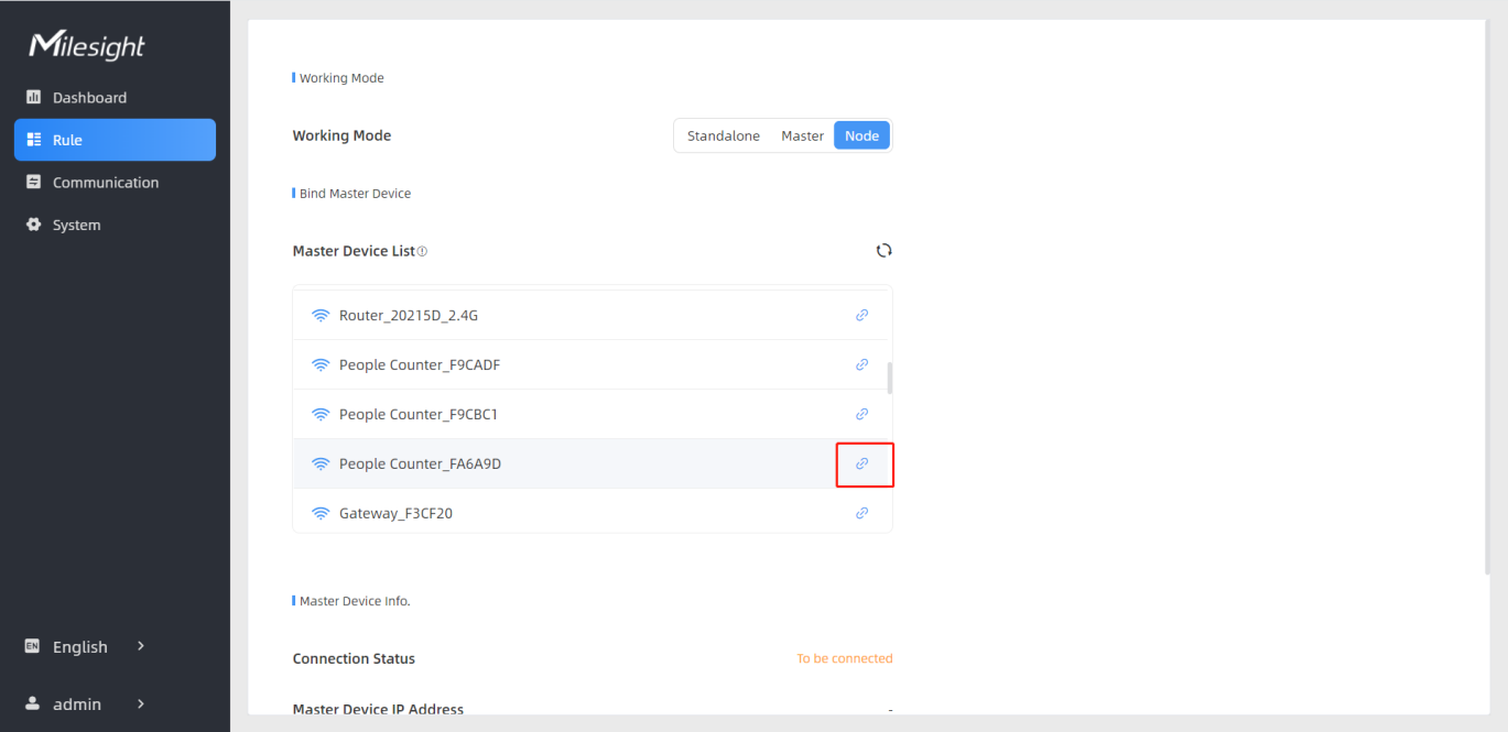
Step 3: Find the Wi-Fi access point of master device and connect.
| Parameters | Description |
|---|---|
| Connection Status | Show the connection status between the node device and master device. |
| Master Device IP Address | Show master device’s IP address. When this IP address is under the same network with the node device, the node device can be bind to the master device. |
| Master Device SN | Show the master device’s serial number. |
| Master Device Name | Show master device name. |
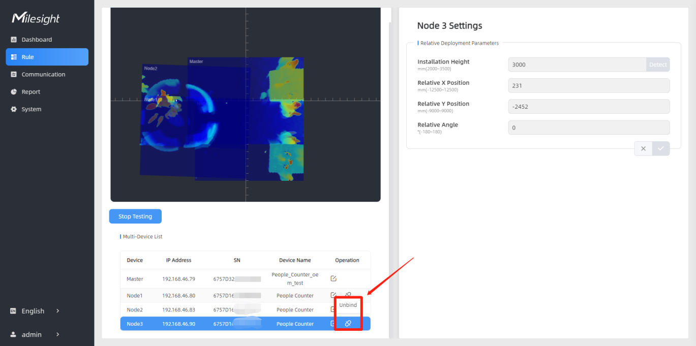
| Unbind Master Device | Click Unbind to release the connection status, this device will be deleted from the list of the master device. |
Master Device Setting
| WLAN Channel | Video Stream | Static Image/No Image | Counting Inaccuracy |
|---|---|---|---|
| Occupied Channel | Not Support | ≤ 6.5m | > 6.5m |
| Idle Channel | ≤8m | ≤10m | >10m |
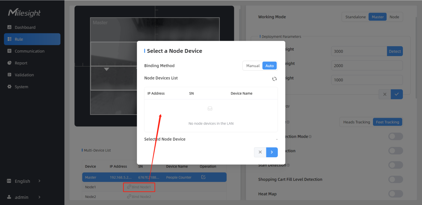
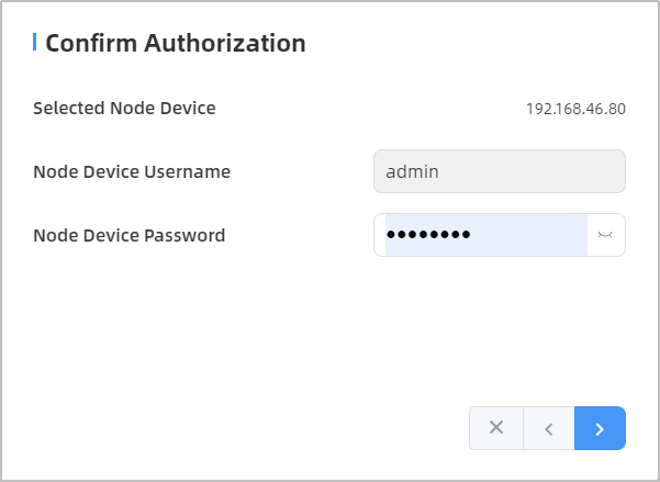
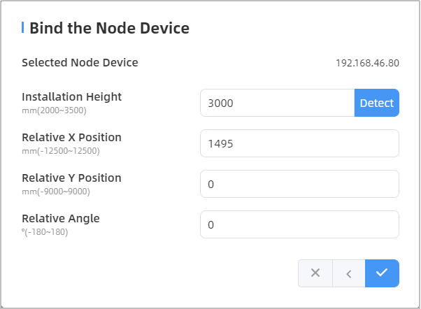
Step 4: Select the node device and type the login password of the node device.
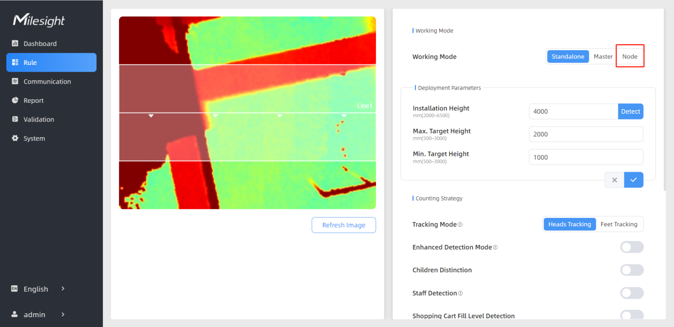
Step 5: Fill in the installation height of a node device and relative position information if these parameters are already measured. If not, save default settings and skip to Step 6.
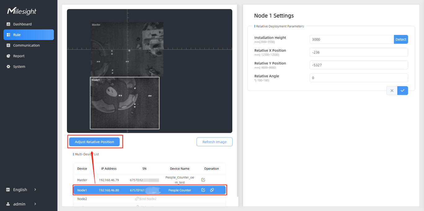
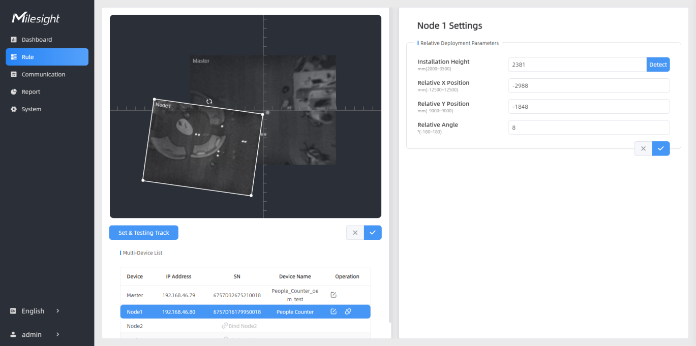
Drag the live view of node device to adjust the location and angle, and the relative position parameters will change automatically as your operations. Besides, users can also adjust the size of this live view.
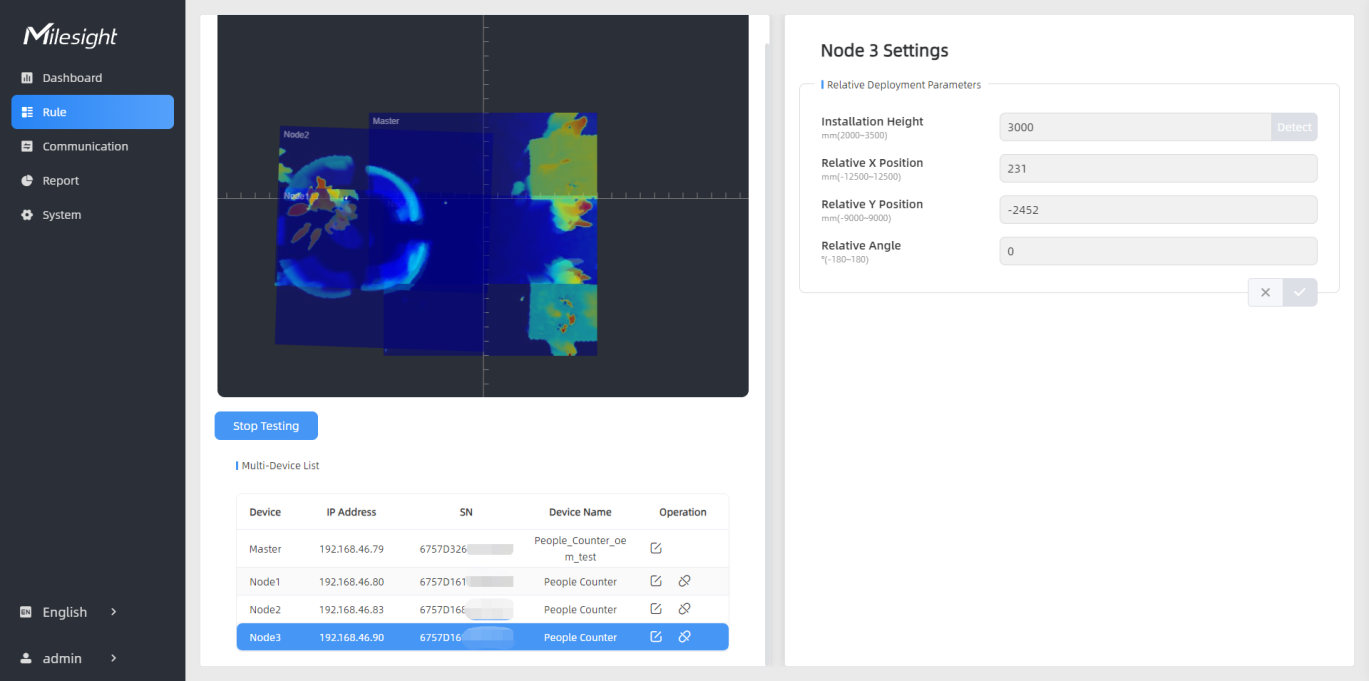
Step 8: When all settings are completed, users can draw detection lines and even U-turn areas on the new stitching live view the same as standalone mode devices.