Installation
Important: Before installation, make sure that the product
is only used for fan coil systems with 100-240V and meets the maximum current
requirements (resistive 4A, inductive 3A, capacitive not support).
Installation Locations
It is necessary to select the installation locations for data source to collect the correct temperature and humidity data, and achieve the accurate control. The section will take internal data source as example to describe the best installation locations.
When using built-in sensors, it is suggested to install the thermostat about 5 ft.
(1.5m) above the floor in an area with good air circulation at average
temperature.
Note: If installation in an appropriate
location is not possible, please select other data sources. For more info, click
Data Source Selection.
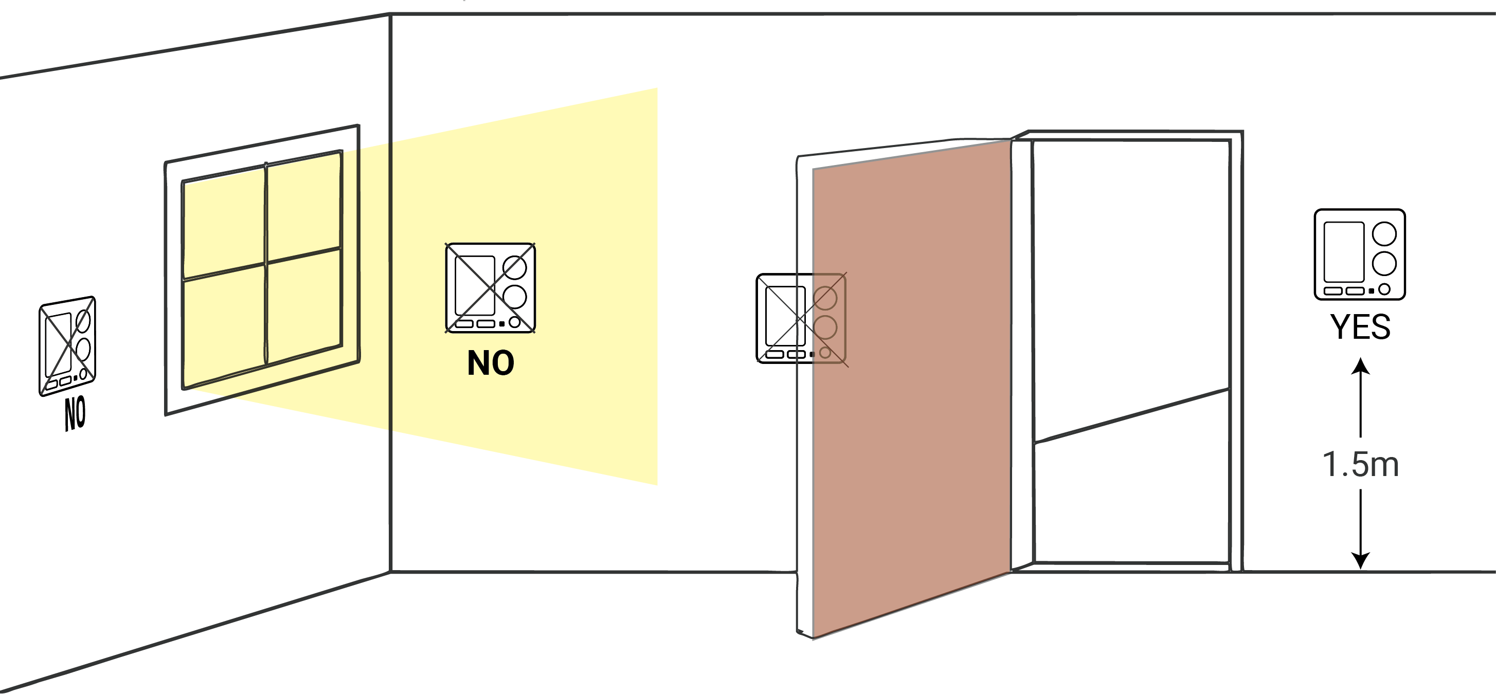
Do not install the device where:
- Close to hot or cold sources like hot or cold air ducts;
- The place in direct sunlight;
- Dead spots or drafts (behind the doors and in corners);
- In areas that do not require conditioning;
- Close to concealed chimneys or pipes;
- Close to metal objects and large obstacles which affect the wireless transmission;
- The place with lots of electromagnetic interfaces;
- The place where strong vibration may happen or easy to be subjected to physical shock.
Device Installation
- Wall Screw Mounting
- Applicable: Standard 86mm pattress box or European 60mm pattress box.
1. Switch off the power to your system.
2. Remove the wire terminal from the device, then screw the wires to the wire terminals.Note:- If hard plastic wires are used, it must be bent to an appropriate angle in advance;
- Unused cables must be insulated and secured.
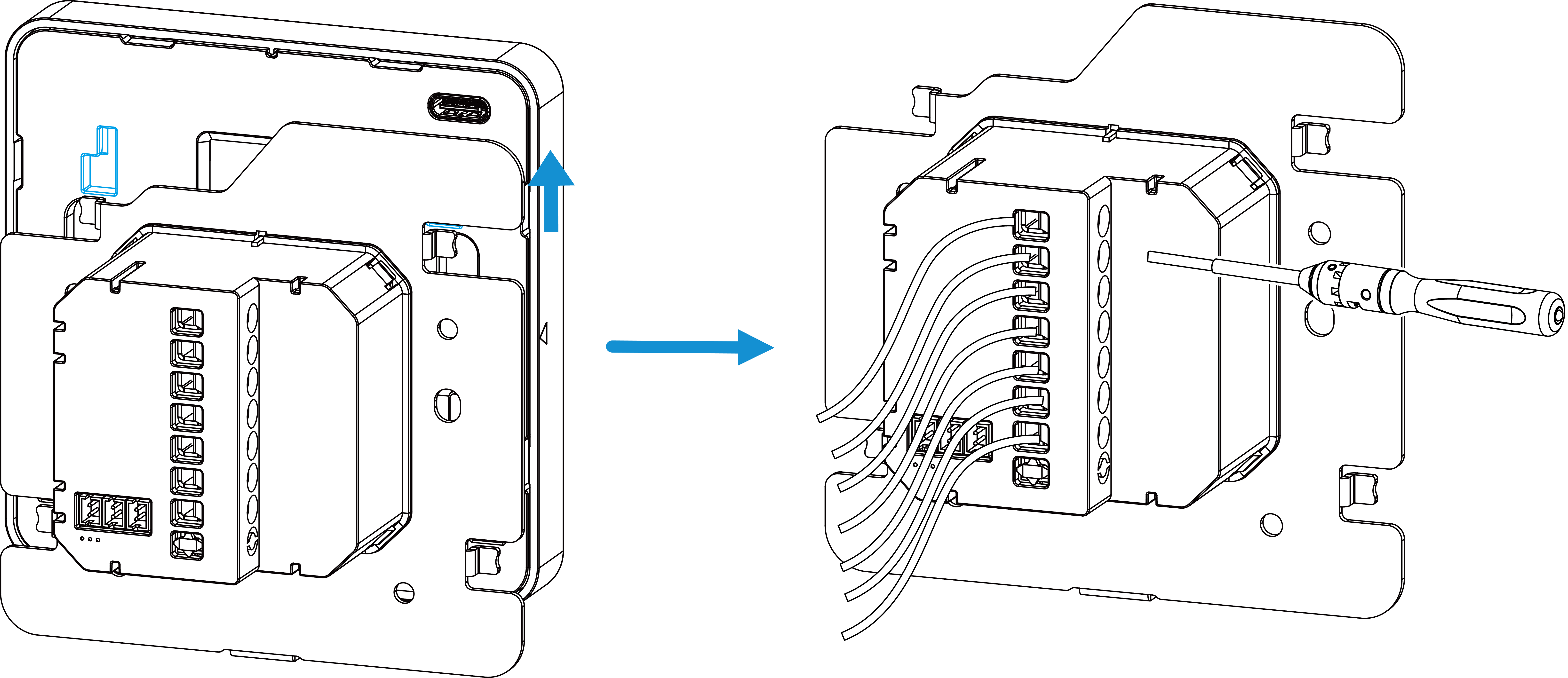 3. Fix the wire terminal to the pattress box via wall screws.
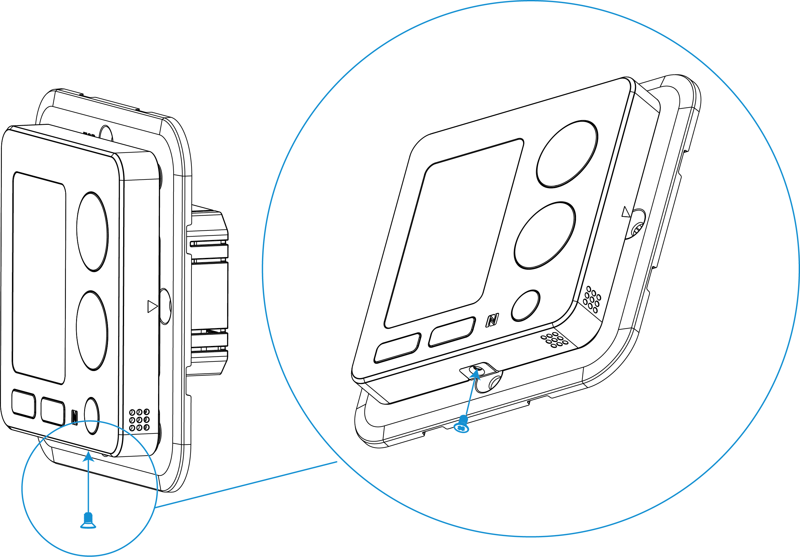
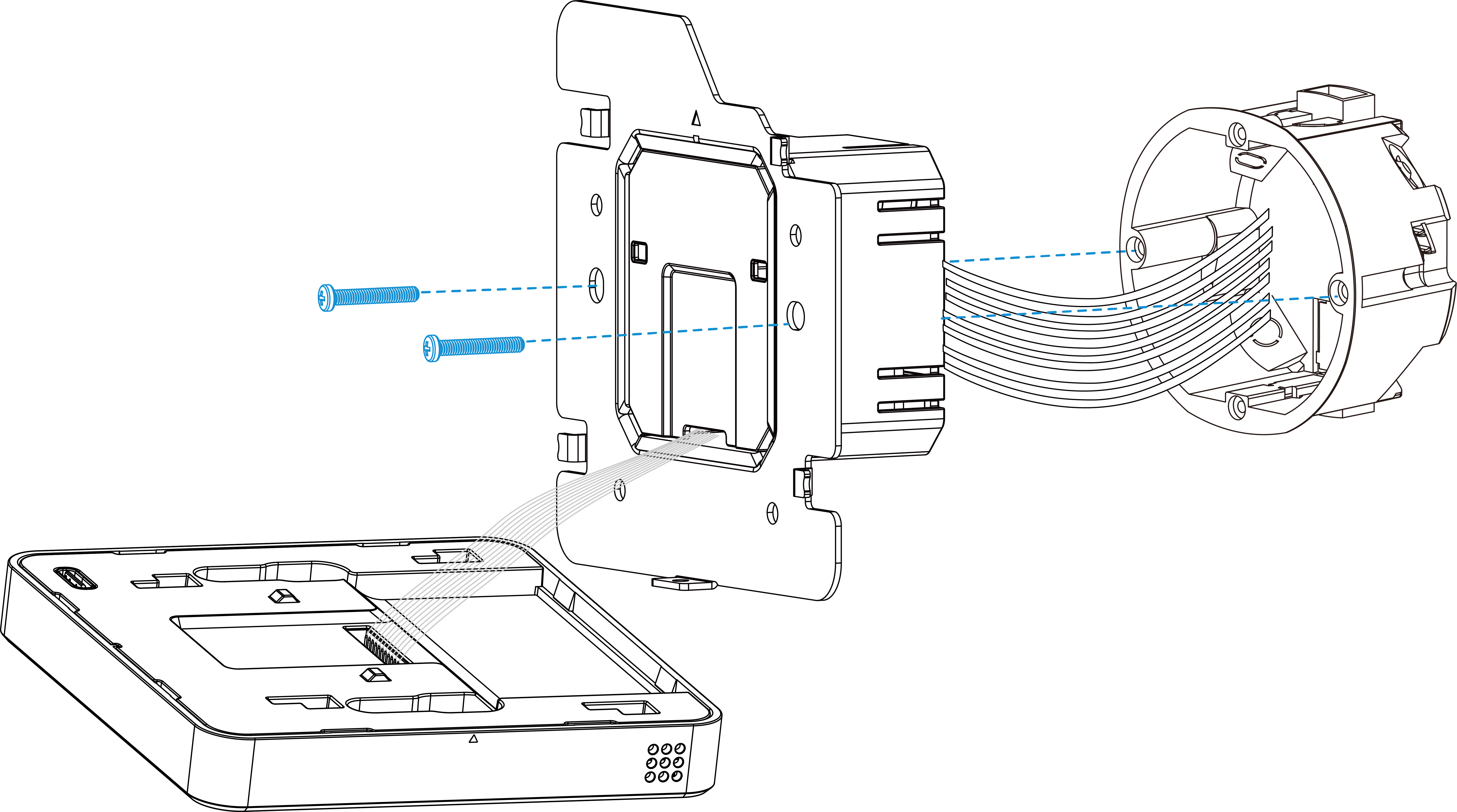 4. Fix the device to the wire terminal with the fixing screw.
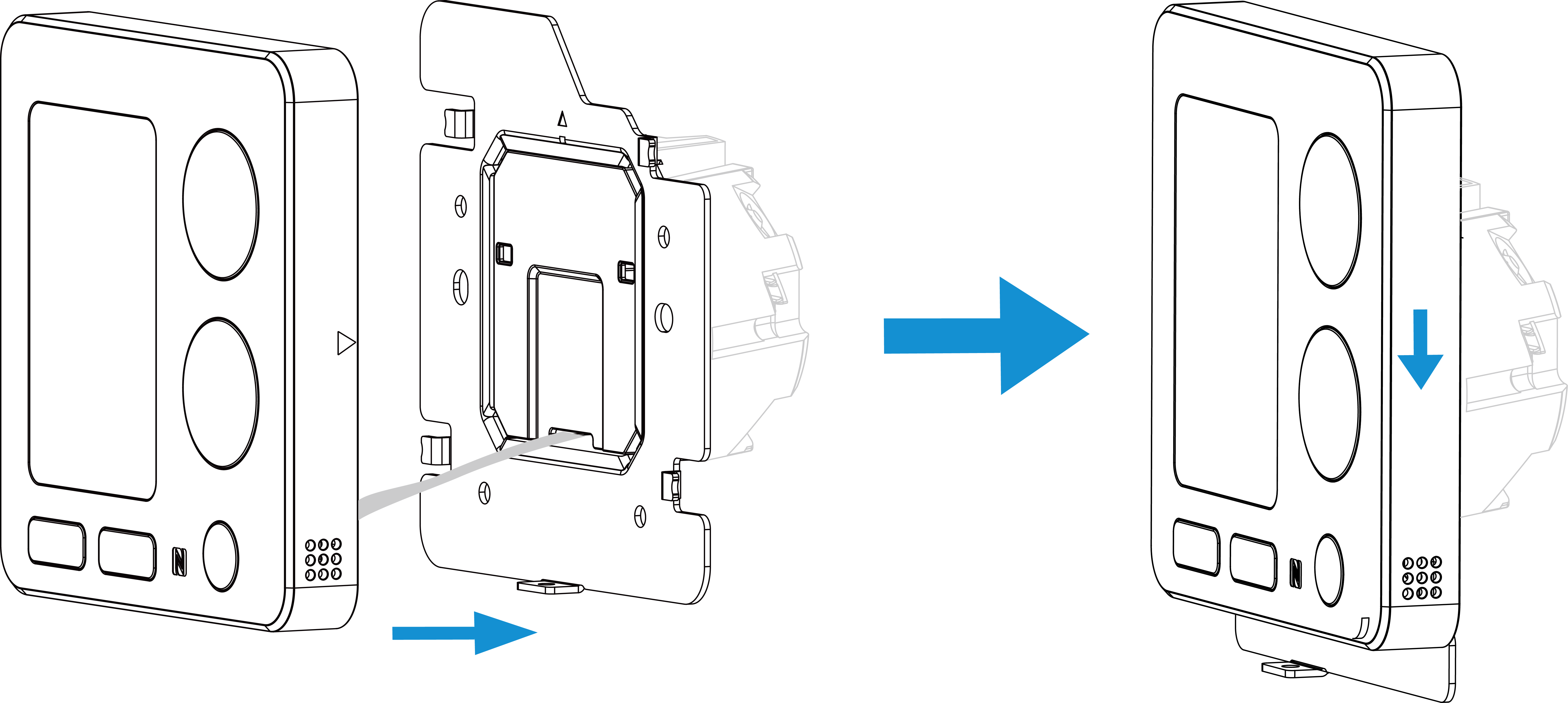
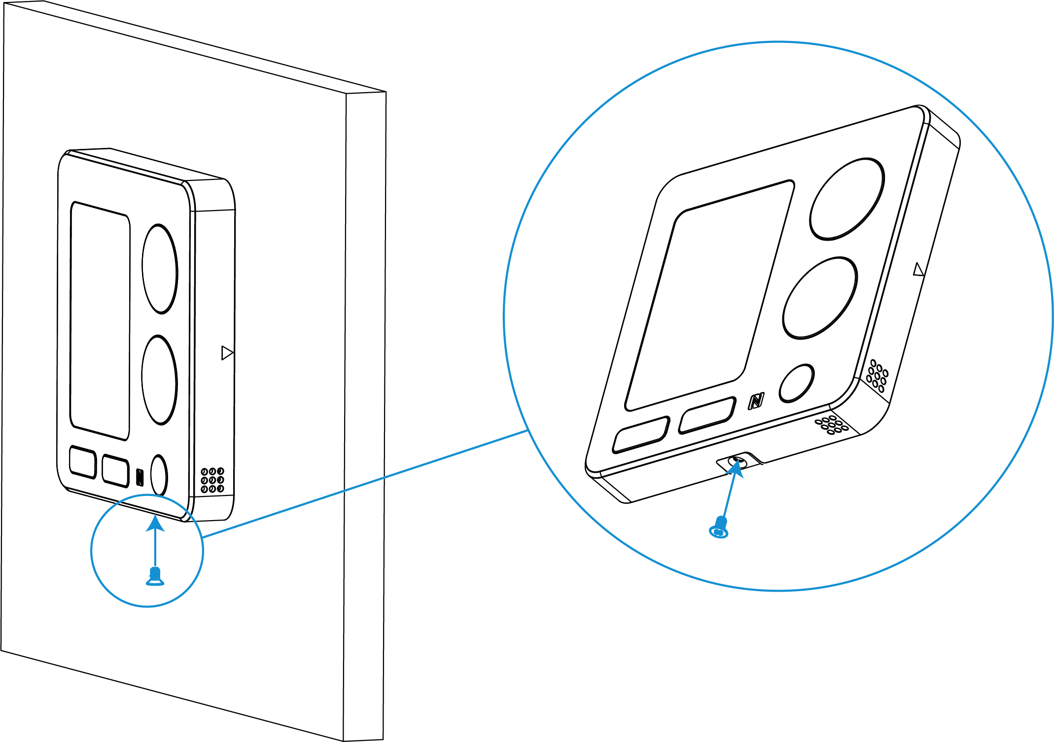
5. Switch the power back on. The screen will flash if the device is powered well.
- Wall Plate Mounting (Optional)
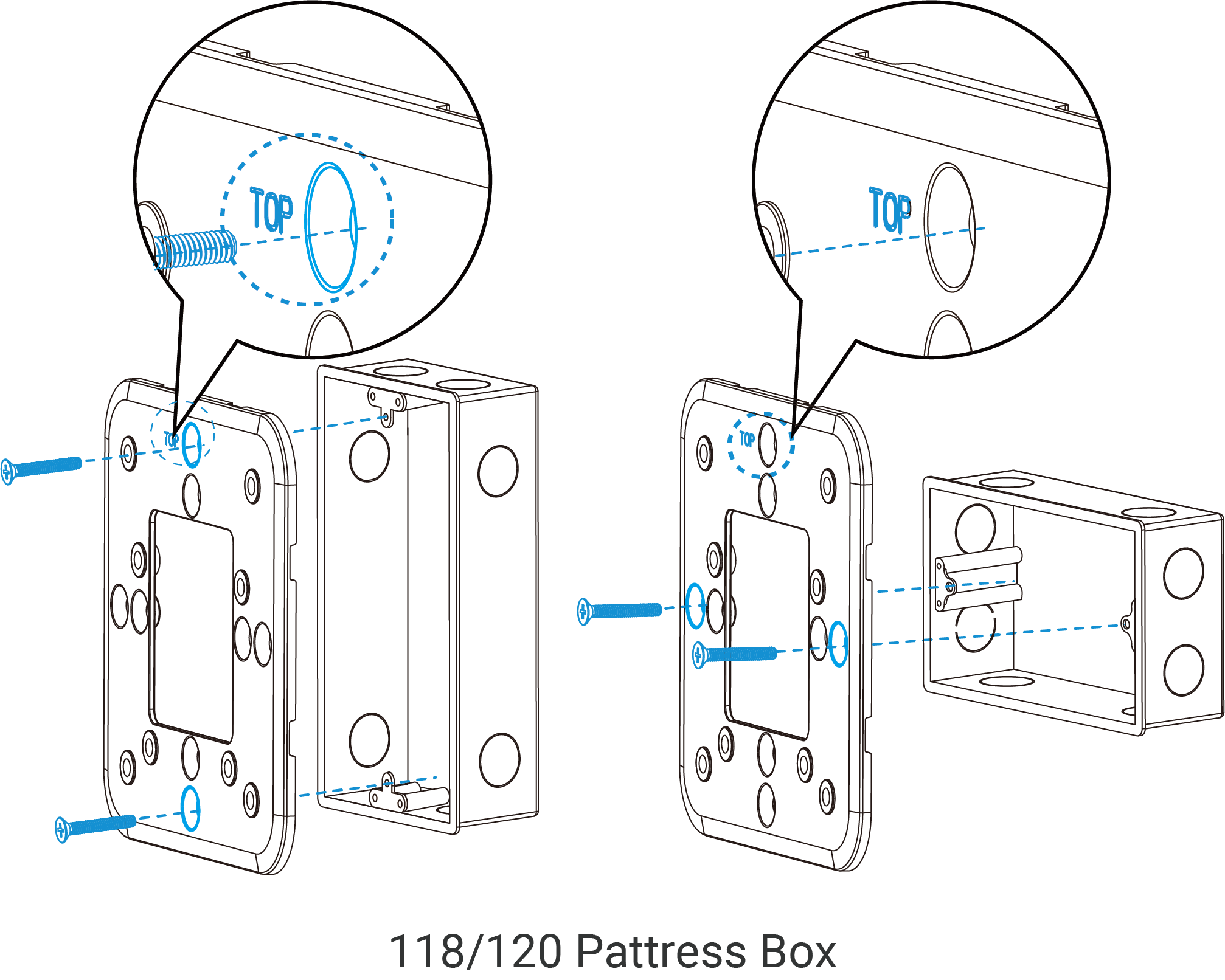
- Applicable: Standard 86mm pattress box, European 60mm pattress box,
118/120mm pattress box.
1. Switch off the power to your system.
2. Fix the wall plate to the pattress box.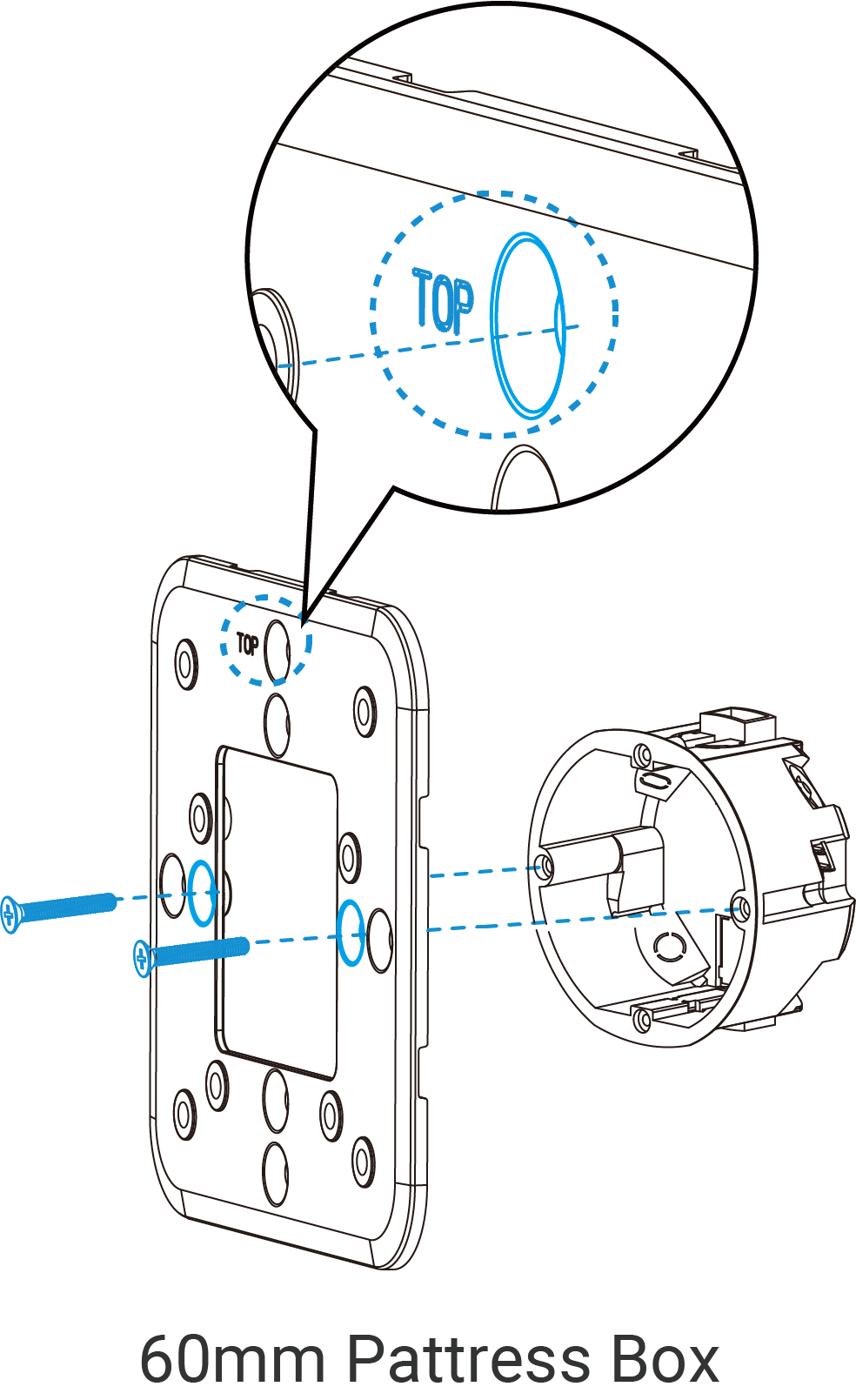
 3. Remove the wire terminal from the device, then screw the wires to the wire terminals.Note:
- If hard plastic wires are used, it must be bent to an appropriate angle in advance;
- Unused cables must be insulated and secured.
4. Fix the wire terminal to the wall plate via screws.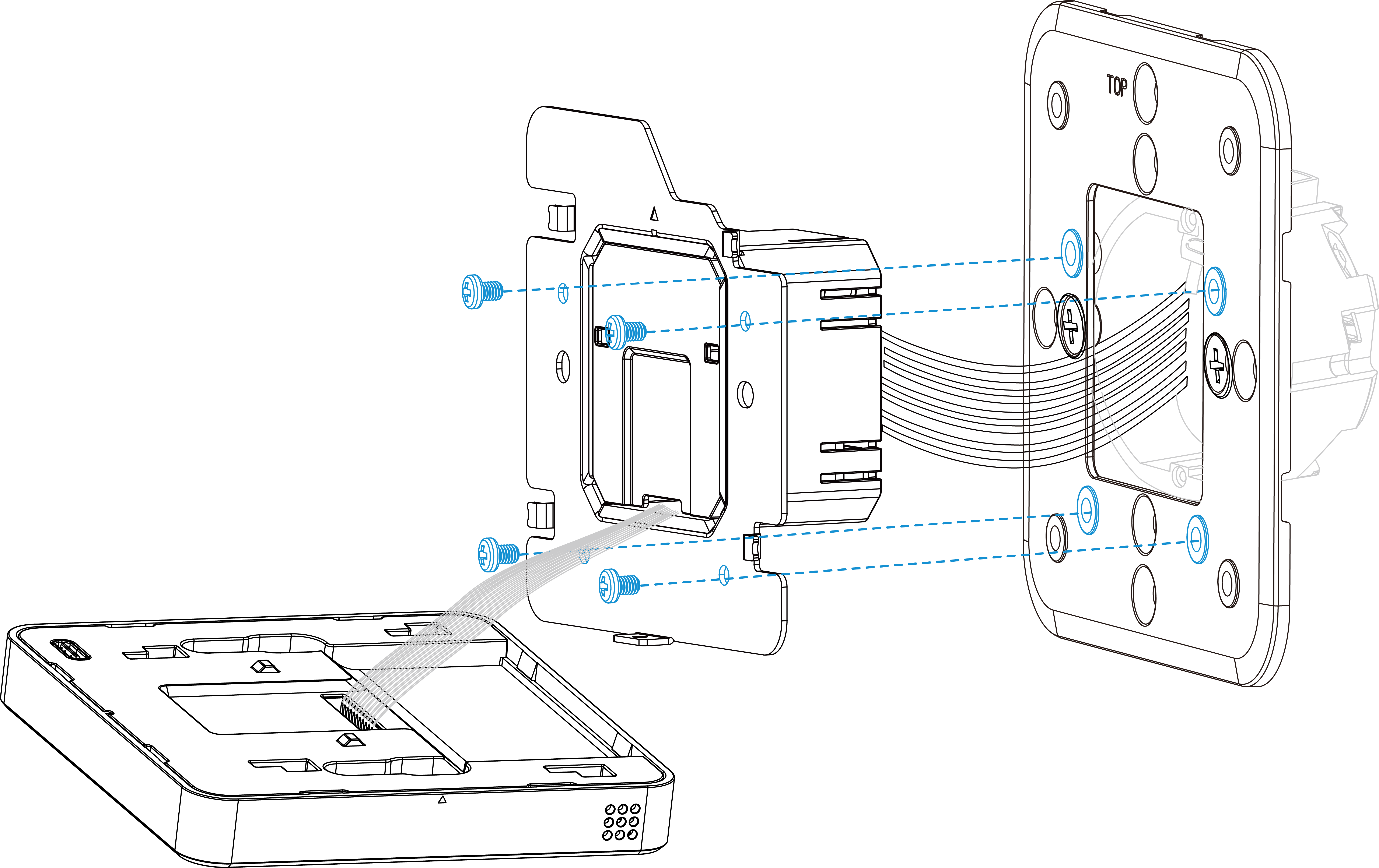 5. Fix the device to the wire terminal with the fixing screw.
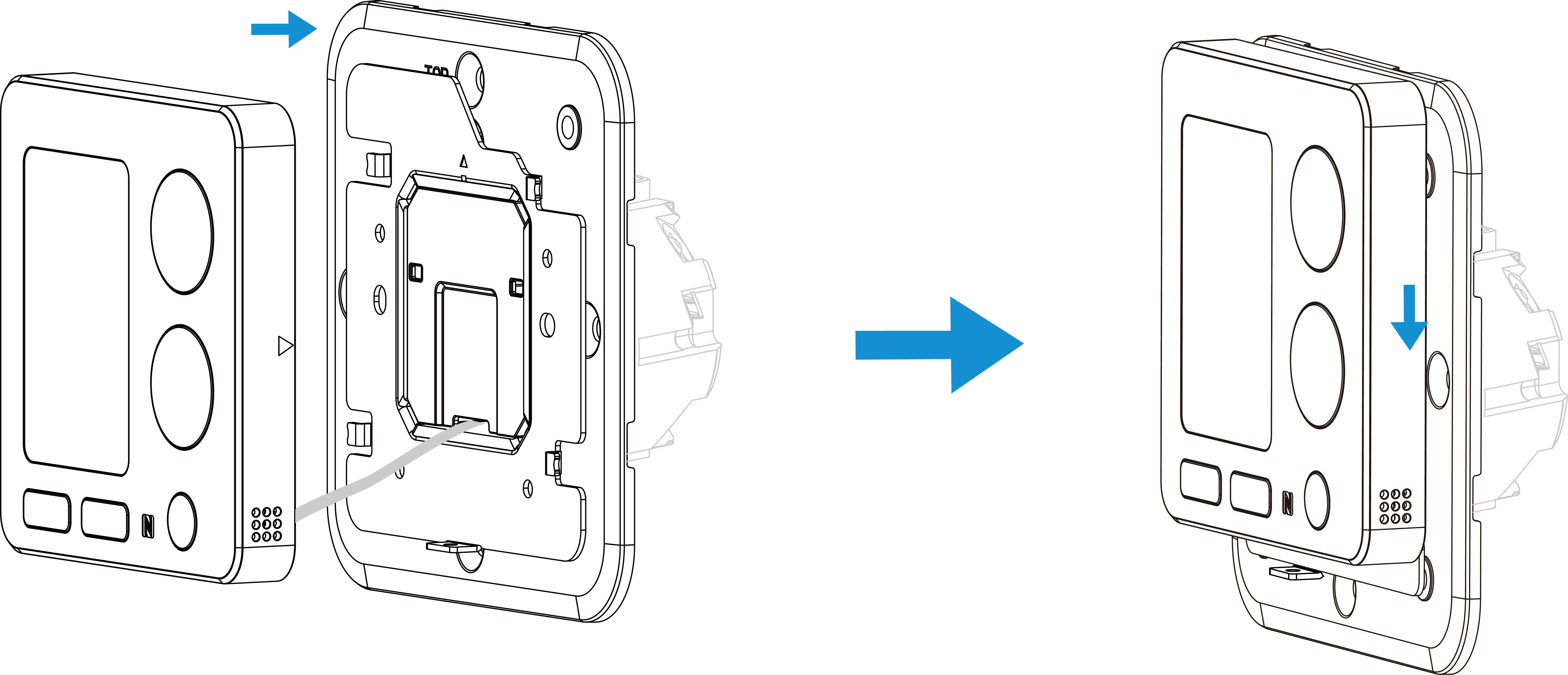
 6. Fix the decorate plate to the device.
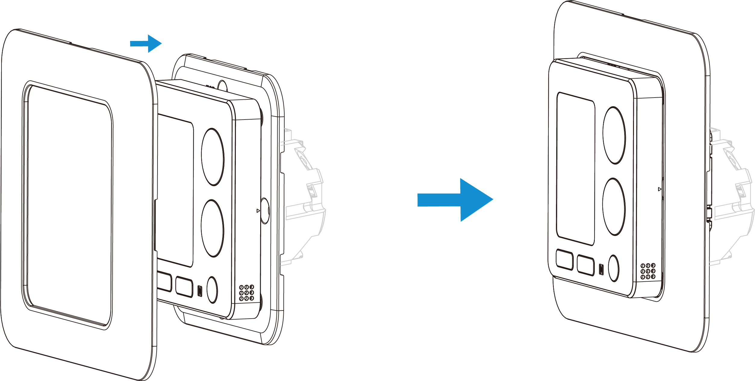
7. Switch the power back on. The screen will flash if the device is powered well.
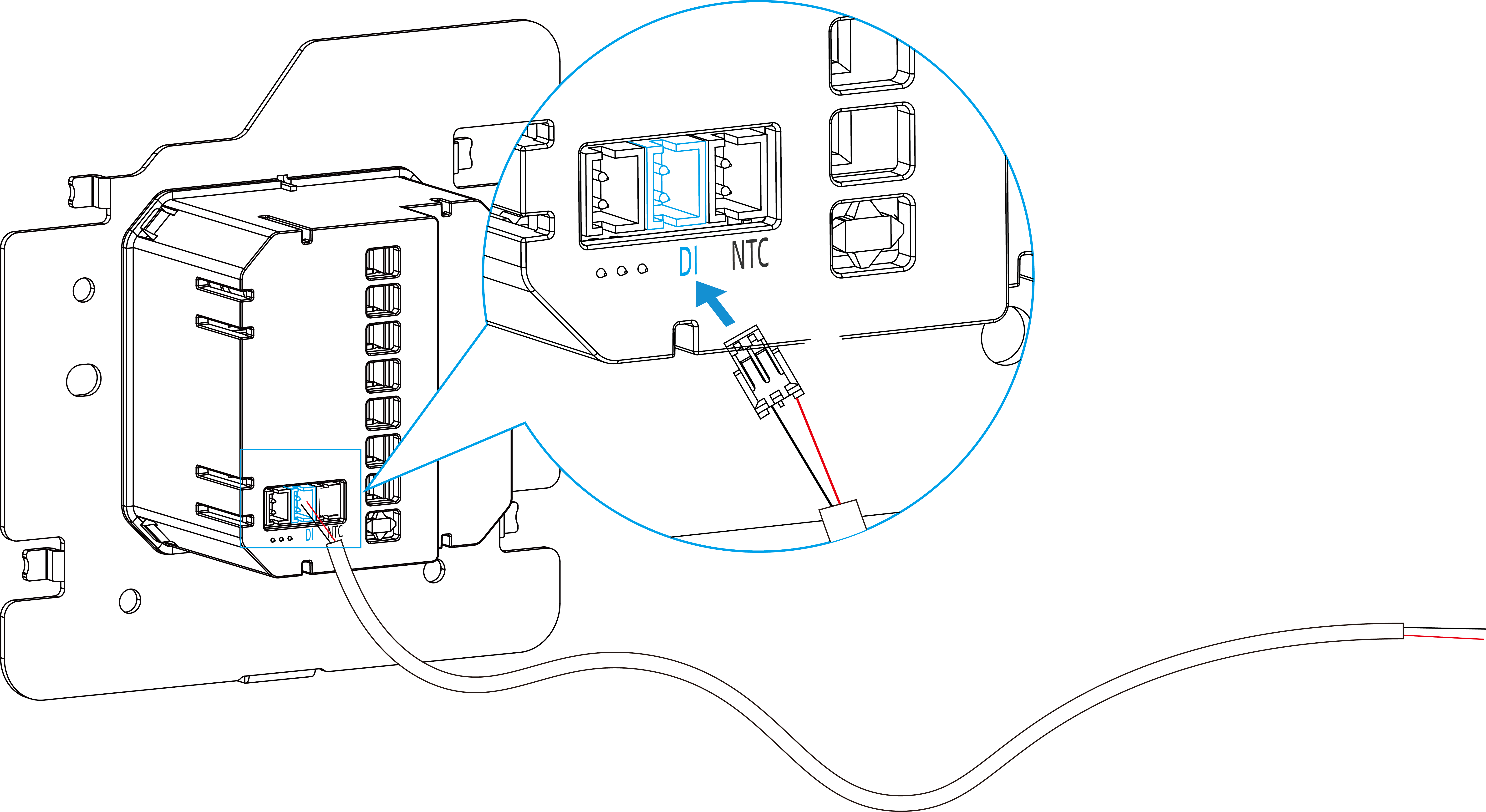
DI Installation (Optional)
The device supports connecting DI to key cards, magnetic switches, and other
physical switches via the signal cable.
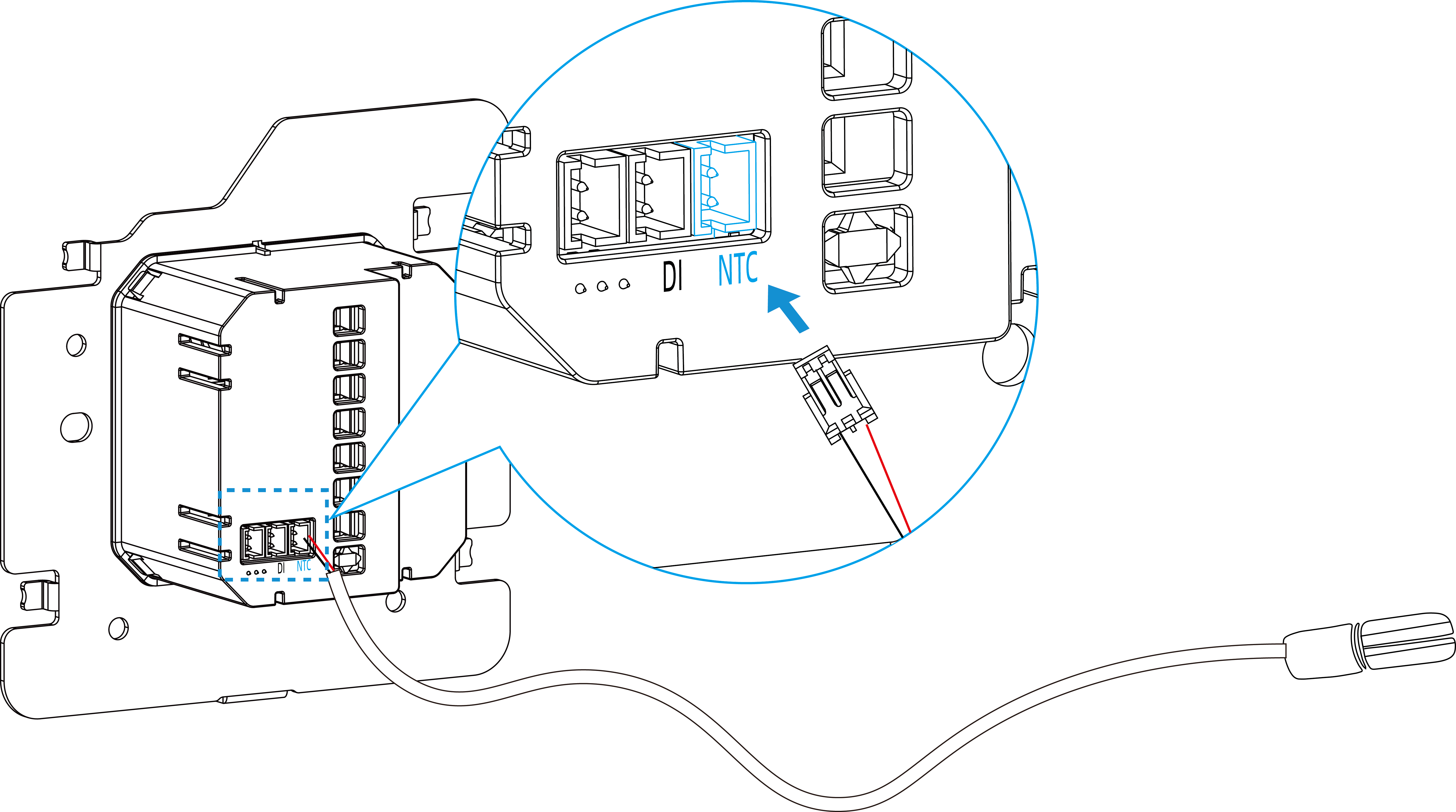
NTC Sensor Installation (Optional)
The device equips with a NTC input for optional NTC sensor connection. If you already
have NTC sensors, please provide the spec of the sensors to Milesight to check the
compatibilities.