Network Server
The gateway can work as a LoRaWAN® network server when the packet forwarder type is set to Embedded NS. This chapter describes how to use the gateway embedded network server.
General
- On the left bar, select Network Server
page.
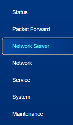
- On the top bar, select General tab.
- Configure the global channel plan parameters as required.
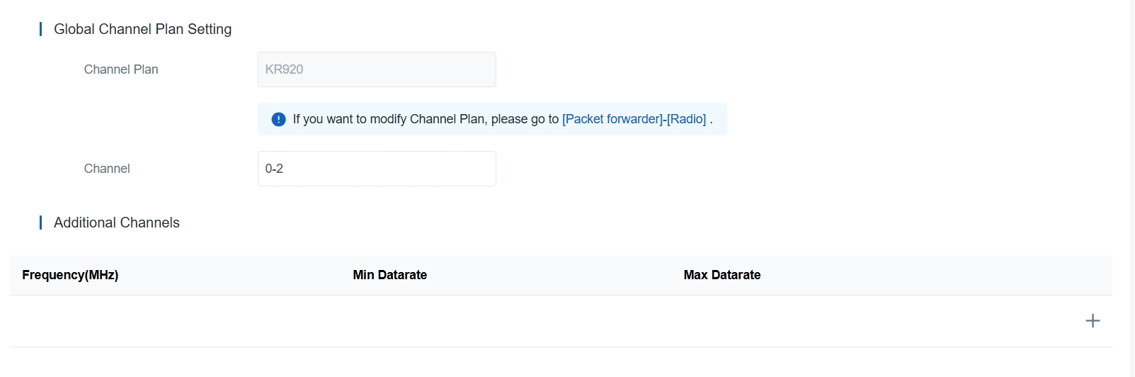
Parameter Description Channel Plan Display the current channel plan. This can be changed in Packet Forward > Radio page. Channel Allow end devices to communicate via specific frequency channels by entering the channel indexes. Examples: 1,40: Enable Channel 1 and 40
1-40: Enable Channel 1-40
1-40, 60: Enable Channel 1-40 and 60
Null: Enable all channelsAdditional Channels Click plus icon to add channels not defined by the LoRaWAN® Regional Parameters. This parameter only works with channel plans other than US915/AU915/CN470. - Click Save & Apply to save the settings.
Devices
This section is used to add and manage LoRaWAN® end devices. The gateway supports up to 20 devices.
- The end device class type is Class A or Class C.
- Obtain the device information from the vendor.
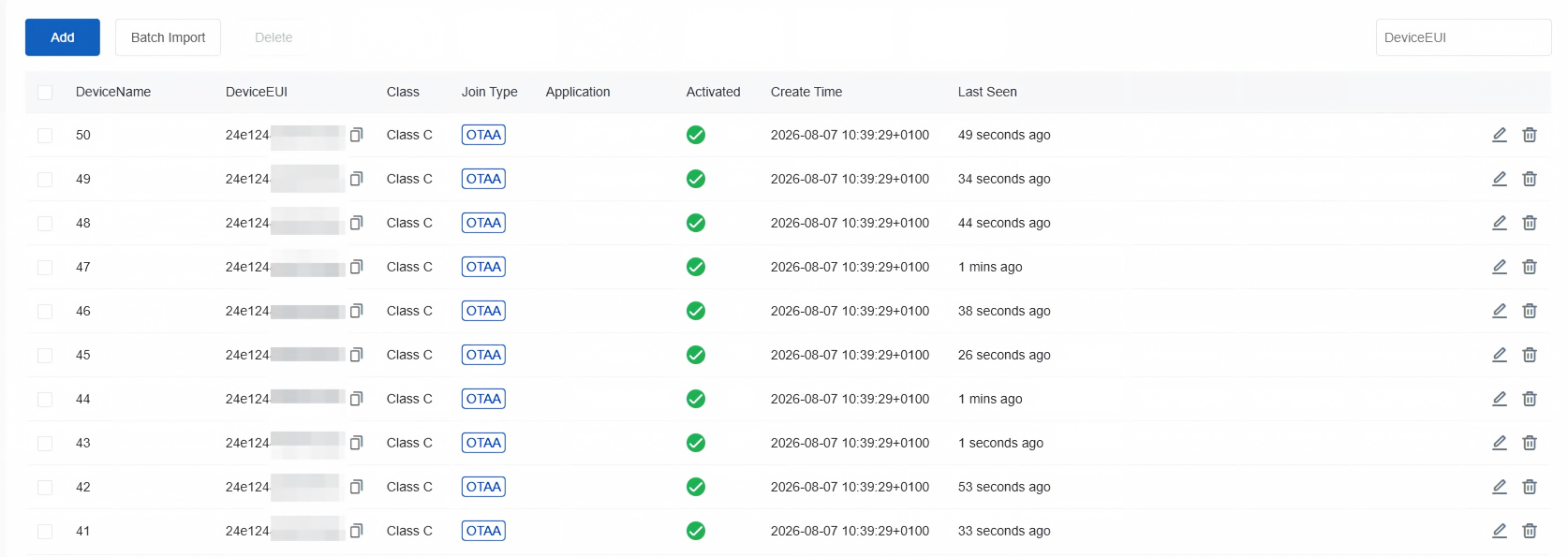
The gateway supports adding a device individually or batch importing devices. Please select one method to add devices.
- Add a Single Device
-
- On the left bar, select Network Server
page.
- On the top bar, select Device tab.
- Click Add and configure the device related
parameters.
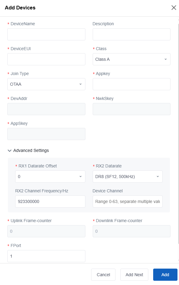
Parameter Description Device Name Define a unique name for the device. Description For noting this device. Device EUI The unique 16-digit hexadecimal EUI of the device. Class Select the device class type from Class A and Class C. Join Type Select the device join type from OTAA and ABP. App Key When join type is OTAA, set the 32-digit hexadecimal Application Key value. DevAddr When the join type is ABP, set the 8-digit hexadecimal Device Address. NwkSKey When the join type is ABP, set the 32-digit hexadecimal Network Session Key value. AppSKey When the join type is ABP, set the 32-digit alphanumeric Application Session Key value. Advanced Settings RX1 Datarate Offset: The offset used to calculate the RX1 data rate based on the uplink data rate. RX2 Datarate: The data rate of RX2 window. RX2 Channel Frequency: The frequency of RX2 window. Device Channel: Allow the device to communicate via specific frequency channels by entering the channel indexes. This parameter only works with CN470/US915/AU915 channel plans. Examples: 1,40: Enable Channel 1 and 40
1-40: Enable Channel 1-40
1-40, 60: Enable Channel 1-40 and 60
Null: Enable all channelsClass C ACK Timeout: The time to wait for a downlink response from class C devices. If no response is received within this time, the gateway will retransmit the downlink command. Uplink Frame-counter When the join type is ABP, set the uplink frame-counter. Downlink Frame-counter When the join type is ABP, set the downlink frame-counter. FPort FPort (Frame Port) is a single-byte field in the MAC payload that identifies the type or destination of the data. For Milesight end devices with default settings, the FPort is 85. Frame-counter Validation Enable or disable to prevent replay attacks. - Click Add to complete the addition, or click Add Next to add a new device.
- Check if the device status is activated. If not, navigate to Network Server > Packets to check for communication between the device and the gateway.
- On the left bar, select Network Server
page.
- Batch Import Devices
-
- On the left bar, select Network Server
page.
- On the top bar, select Device tab.
- Click Batch Import.
- In the pop-up window, download the template file and add the
device information to the template file.Note: When editing template files, do not delete the table headers or the instructions at the top.
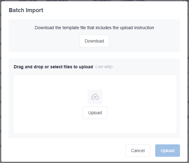
- Select the device file to upload or drag the file to the target box.
- Click Upload. If upload failed, an error message will pop-up; if upload successfully, the devices will be added to the Devices page.
- On the left bar, select Network Server
page.
Application
- Add an Application
-
- On the left bar, select Network Server
page.
- On the top bar, select Application tab.
- Click Add to add a new application.
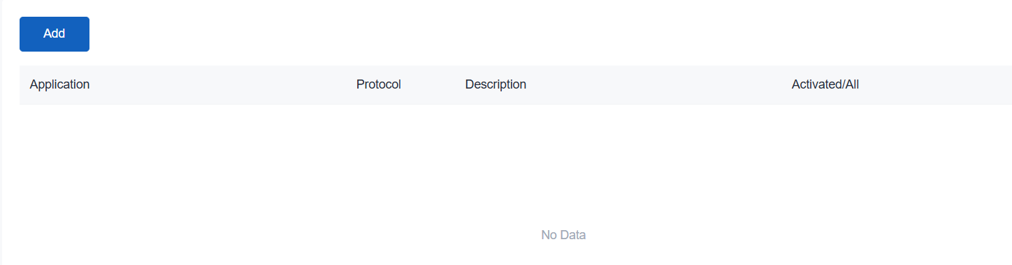
- Configure the application basic info, then click
Next.
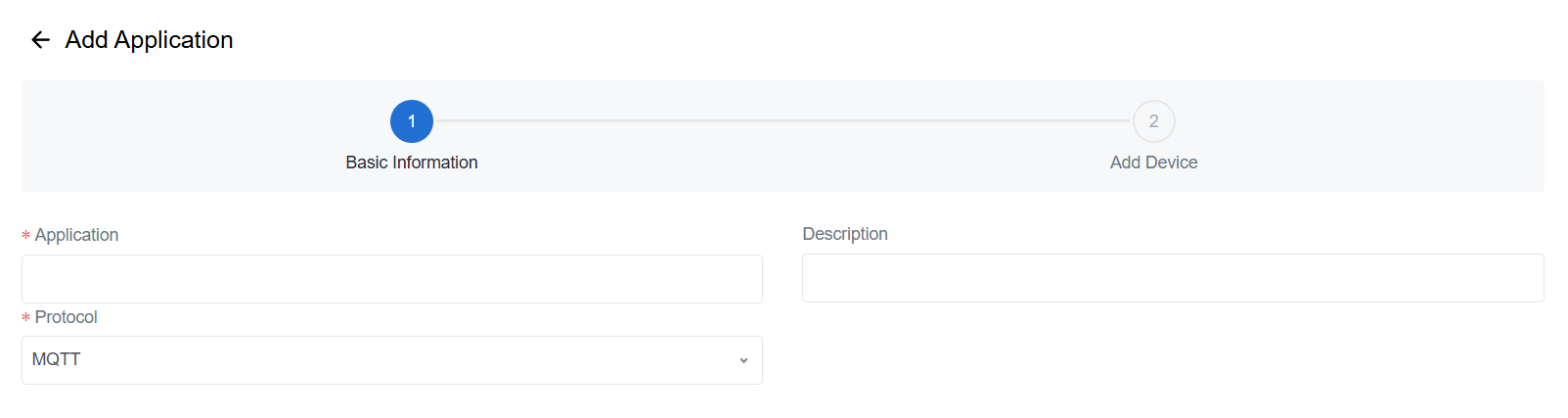
Parameter Description Application Define a unique name for the application. Description For noting this application. Protocol Select the transmission protocol to connect to the remote server from MQTT, HTTP and HTTPS. - Select the devices to add to this application, or click plus
icon in the top right to add a new device. Then click
Save.
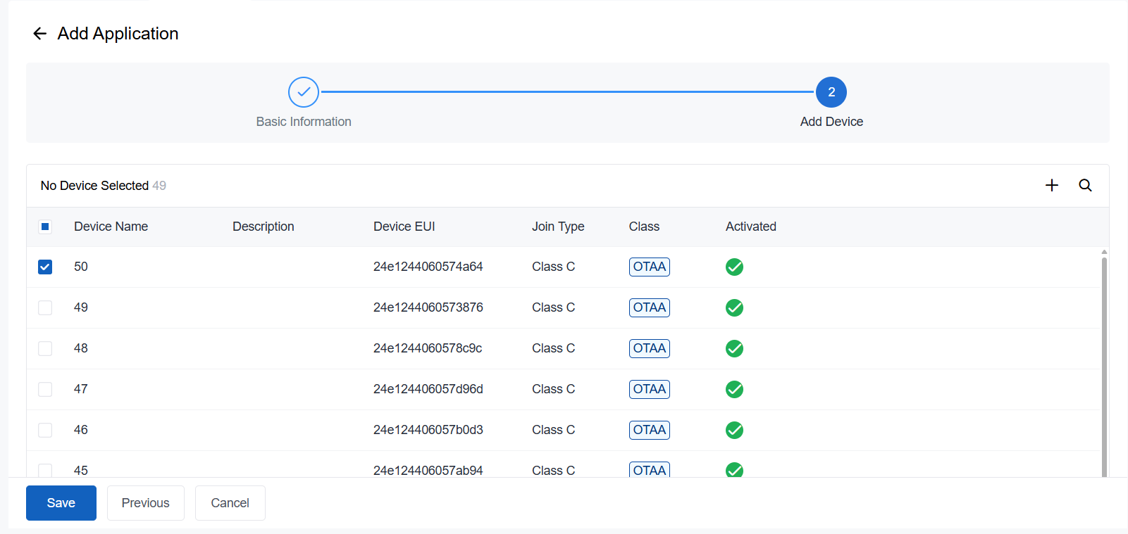
- Navigate Device page to add or delete devices, or navigate to HTTP/HTTPS/MQTT page to configure server info. For details, refer to the following content.
- On the left bar, select Network Server
page.
- Manage Device in an Application
-
- Select the desired application, click
 .
. - Under Device tab, click Add to add devices to this
application, or select target devices and click Delete to
remove them from the application.

- Select the desired application, click
- Configure MQTT/HTTP/HTTPS Settings
-
- Select the desired application, click
.
- Under MQTT/HTTP/HTTPS tab, configure the server
parameters.
- HTTP/HTTPS
-
Parameter Description Name Define a unique name for this server. Enable Enable or disable to forward data to a HTTP(s) server. HTTP Headers Click plus icon to add an HTTP header name and value. Data Topic Set the URL to send different types of data. For more details, refer to MQTT&HTTP Application Guide. Uplink Data: Device data uplinks.
Join Notification: Device join request packets.
ACK Notification: ACK notification after sending confirmed downlink commands to LoRaWAN® devices.
Gateway Info: Gateway basic information and network status.
- MQTT
-
Parameter Description Name Define a unique name for this server. Enable Enable or disable to set up the communication with a MQTT broker. General Broker Address The IP address or domain name of the MQTT broker. Broker Port The service port of the MQTT broker. Client ID The unique identifier of the gateway. Keep Alive Interval The interval to send heartbeat packets regularly to keep alive. Data Retransmission When enabled, it supports storing up to 100 packets when the network is disconnected and re-transmits the data after network recovery. Auto Reconnect If the connection is lost, the attempt to reconnect will be made automatically.
Reconnect Period: The interval to reconnect the server.
Clean Session When enabled, the connection will create a temporary session, and all information will be lost when the client is disconnected from the broker; when disabled, the connection will create a persistent session that will remain and save offline messages until the session logs out over time. User Credentials Enable or disable to authenticate with username and password. Username: The username for authentication.
Password: The password for authentication.TLS Enable or disable TLS authentication. Mode: Select the certificate mode as CA Signed Server Certificate to use preloaded certificates, or Self Signed Certificates to import the custom CA certificates(.crt or .pem), client Certificates(.crt) and client key(.key) for verification.
SSL Security: After enabled, the gateway will verify the certificate’s validity.Tip: If MQTT broker type is HiveMQ, enable TLS and set the mode as CA signed Server Certificate.Last Will and Testament Enable or disable sending a will message. The last will message will be sent automatically when the MQTT client is disconnected abnormally. It is typically used to send device status information or notify other devices or proxy servers of the device’s offline status. Last-Will Topic: The topic to receive last will messages.
Last-Will QoS: QoS0, QoS1 and QoS2 are optional.
Last-Will Retain: Enable or disable to set last will message as retain message.
Last-Will Payload: The content of the last will message.Data Topic Data Type The data type to communicate with MQTT broker. For more details, refer to MQTT&HTTP Application Guide. Uplink Data: Receive device uplink packets.
Downlink Data: Send downlink commands to devices.
Join Notification: Receive device join request packets.
ACK Notification: Receive ACK packets after sending confirmed downlink commands to devices.
Gateway Info: Receive gateway basic information and network status.
Request data: Send request commands to enquire or configure the gateway.
Response data: Receive the replies after sending request to Request data topic.Topic Topic name of the data type used for publishing. Period Display the report condition of the uplink data. Among them, Gateway Info supports configuring the report period. Retain Enable or disable to set the latest message of this topic as retain message. QoS QoS0, QoS1 or QoS2 is optional. QoS 0 –Only Once
This is the fastest method and requires only one message. It is also the most
unreliable transfer mode.
QoS 1 –At Least Once
This level guarantees that the message will be delivered at least once, but
may be delivered more than once.
QoS 2 –Exactly Once
QoS 2 is the highest level of service in MQTT. This level guarantees that
each message is received only once by the intended recipients. QoS 2 is the safest and slowest quality of service level.
- Click Save & Apply to save the settings.
- Select the desired application, click
Packets
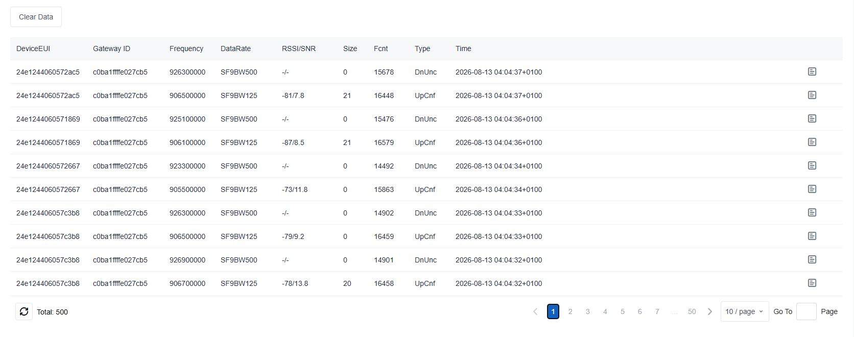
| Parameter | Description |
|---|---|
| Refresh | Update the latest data packet records. |
| Clear Data | Clears all data packet records on this page. |
| Device EUI | The device EUI of the packet. |
| Gateway ID | The ID of the gateway that sends the packet. |
| Frequency | The frequency used to receive or send the packet. |
| Data Rate | The data rate of the packet. |
| RSSI/SNR | The received signal strength and signal-to-noise ratio. |
| Size | The size of the packet. |
| Fcnt | The frame counter of the packet. |
| Type | Display the data type.
|
| Time | The time when the packet was received. |
 |
Opens the packet details. |
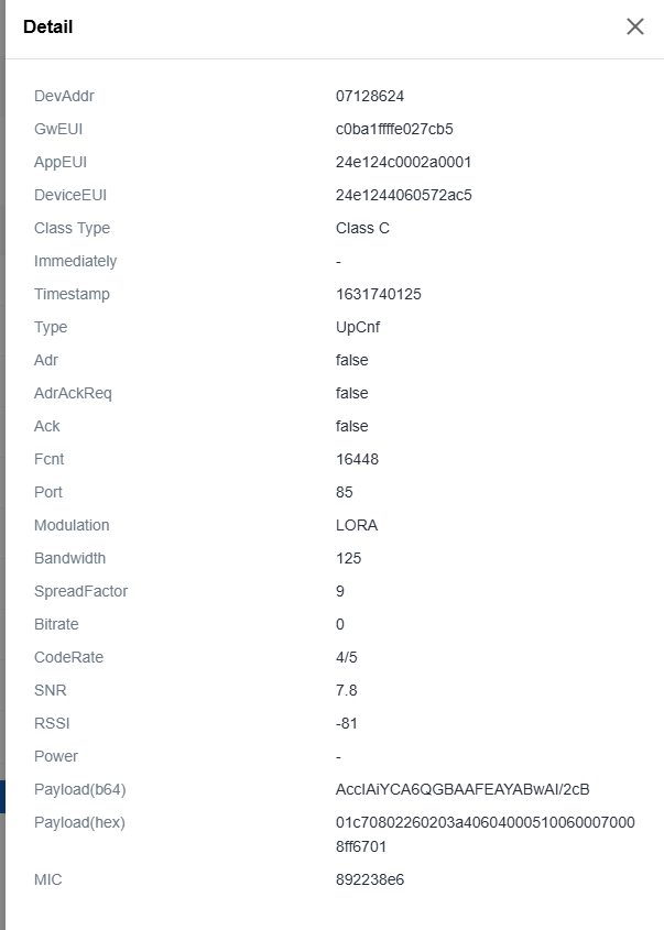
| Parameter | Description |
|---|---|
| DevAddr | The device address of the device that sends the packet. |
| GwEUI | The ID of the gateway that sends the packet. |
| App EUI | The App EUI of the device that sends the packet. |
| Device EUI | The device EUI of the packet. |
| Class Type | The class type of the device that sends the packet. |
| Immediately | Indicates whether the downlink packet is sent immediately. |
| Timestamp | The time when the packet is received after the packet forwarder starts running. Unit: ms. |
| Type | Display the data type.
|
| Adr | Indicates whether the device enables ADR. |
| AdrAckReq | Nodes periodically transmit ADRACKReq to validate that the network is receiving uplink messages. True means the network should respond within ADR_ACK_DELAY. False means ADR is disabled or the network does not respond within ADR_ACK_DELAY. |
| Ack | Indicates whether the packet is an ACK packet. |
| Fcnt | The frame counter of the packet. |
| Port | The FPort used to transmit the packet. MAC commands use port 0; application data uses ports 1-233. |
| Modulation | LORA means the physical layer uses LoRa modulation. |
| Bandwidth | The bandwidth of the frequency channel. |
| Spread Factor | The spreading factor of the packet. |
| Bitrate | The bitrate of the frequency channel. |
| CodeRate | The code rate of the frequency channel. |
| SNR | The signal-to-noise ratio of the packet. |
| RSSI | The received signal strength of the packet. |
| Power | The TX power of the device. |
| Payload (b64) | The payload in Base64 format. |
| Payload (hex) | The payload in hexadecimal format. |
| MIC | The cryptographic message integrity code computed over MHDR, FHDR, FPort, and the encrypted FRMPayload. |