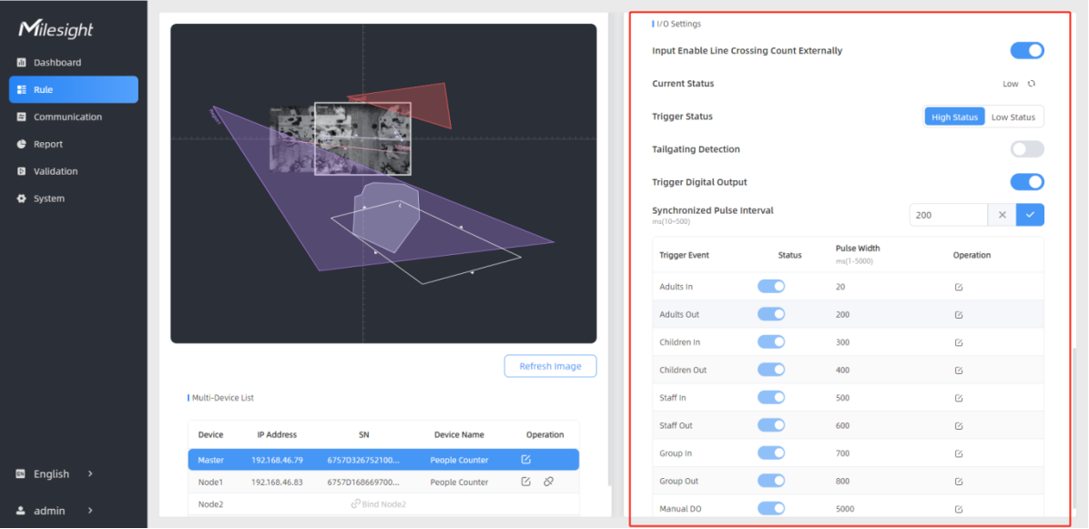
I/O Settings
The device supports Digital Input and Output. Please refer to the wiring diagram and use the Multi-interface Cable to connect the device in the correct sequence.
Input Enable Line Crossing Count Externally
This option is used to enable or disable the counting function for the Digital Input. Only when trigger status is the same as the current status, will the device count the data.
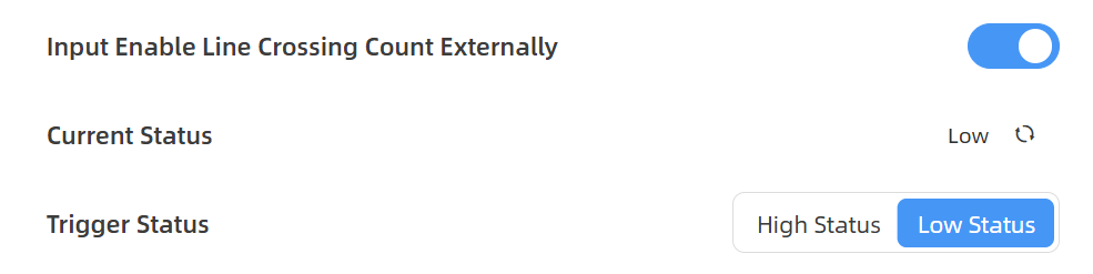
Low Status=two contacts disconnected, High Status=two contacts closure
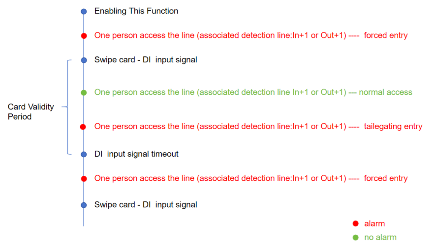
Tailgating Detection
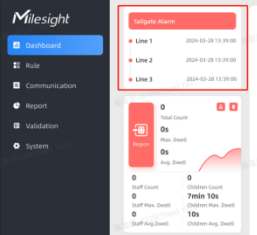
In some places where card swiping is needed at entrances and exits, this function can be enabled to identify unauthorized break-ins, card piggybacking, and sending alerts when an abnormal event is detected. Tailgating Detection supports DO signal output and MQTT/HTTP report alarms.
This function is only recommended for single gate, and it is suggested to draw the detection line around the gate and add u-turn filtering region.
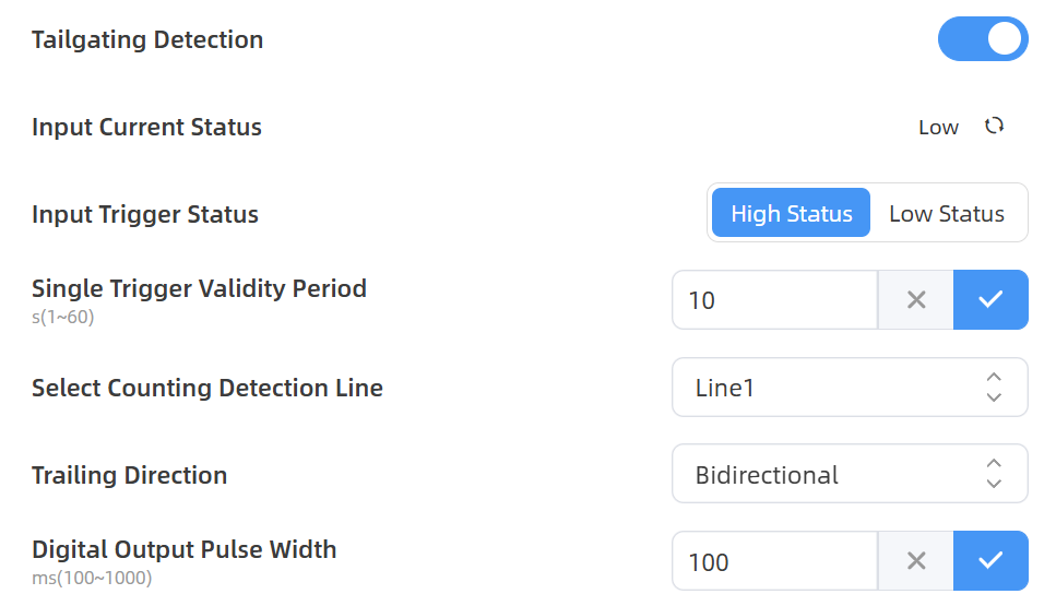
Step 1: Choose High Status or Low Status, configure determines the status of the external input trigger. The device can be configured to use the trigger status as the signal criterion for determining whether a card has been swiped. The trigger level signal of DI must be greater than or equal to 50ms for a valid external input signal.
Step 2: Configure Single Trigger Validity Period, specifying how long the gate stays open to permit passage for one individual.
Step 3: Select Counting Detection Line, which tailgating detection will be applied. An alarm is triggered when the number of crossings exceeds the number of card swipes. Select Trailing Direction, when you want to monitor for tailgating in both the entry and exit directions, select Bidirectional; When you only want to be alerted if tailgating occurs in the entry direction, select Entry Direction, and vice versa.
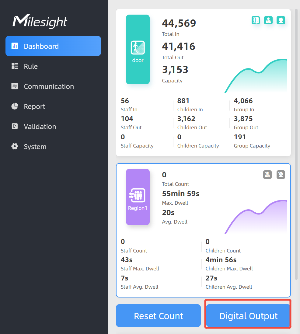
Trigger Digital Output
Step 1: Enable Trigger Digital Output, the digital output will send a preset width of high level.
Step 2: Fill in Synchronized Pulse Interval, the interval between multiple pulses when several people pass through or multiple events trigger at the same time.
Step 3: Enable trigger events.
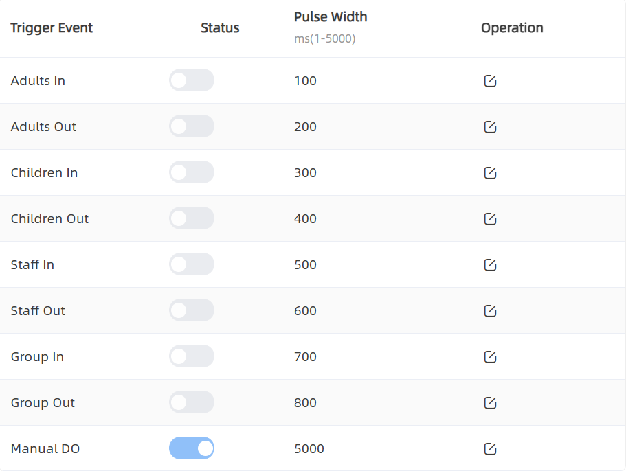
| Parameters | Description |
|---|---|
| Trigger Event | The events to trigger the DOs to
send pulse signals. Note: If staff event
triggers, sending staff pulse signals, does not synchronize
gender or adult pulse signals. |
| Status | Enable or disable the event to trigger the output of a pulse signal. |
| Pulse Width | The duration of the pulse signal. |
| Operation | Click to edit the information. |