Stitch the Master Device and Node Devices
This section describes how to stitch the master device and node
devices, which includes the following procedures:
- Set Working Mode to Master.
- Select a node device.
- Bind the node device to the master device.
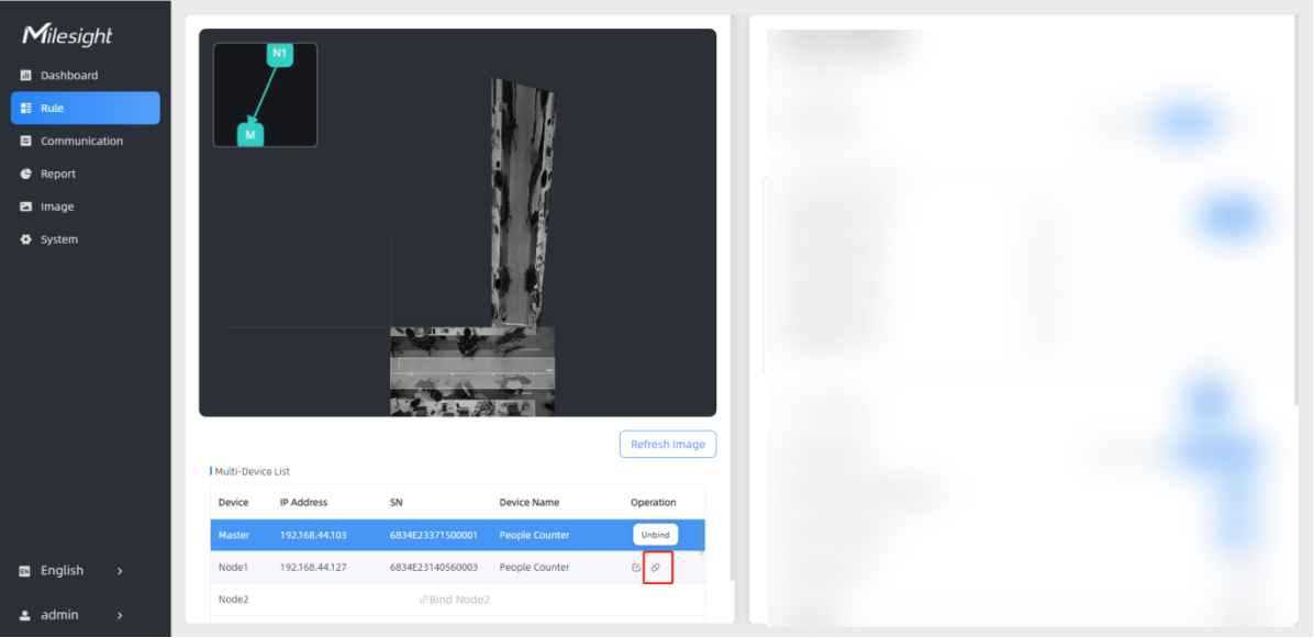
After all stitching configurations are completed, users can draw detection lines and even U-turn areas on the stitched preview using the same method as with standalone devices. Multi-Device Frame and Master Device Frame are displayed on the Dashboard page to view the stitched multi-device preview and the master device preview respectively.
Set Working Mode to Master
- Log into the web GUI of the master device, and click Rule from the left navigation tree.
- In the Working Mode area on the right,
click Master. The Tips information box is displayed.
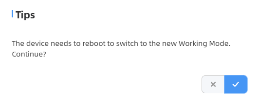
- Click
 to
wait for the device to reboot.
to
wait for the device to reboot.
Select Bind Node Devices
- After the reboot is completed, click Rule from the left navigation tree.
- In the Multi-Device
List area, click Bind Node1. The Select a Node
Device dialog box is displayed.
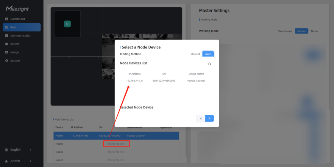
- Select a node device to be added.
- To select a node device manually:
- Click Manual.
- Enter an IP address, HTTP port, user name or password in the corresponding text box.
- Click . The Bind the Node
Device page is displayed.
- To select a node device automatically:
- Click Auto. Then the device automatically uses the multicast protocol to discover the unbound node devices within the same local network. The discovered devices are listed in Node Devices List.
- Select the
node device to be added and click
 . The Confirm
Authorization dialog box is displayed.
. The Confirm
Authorization dialog box is displayed.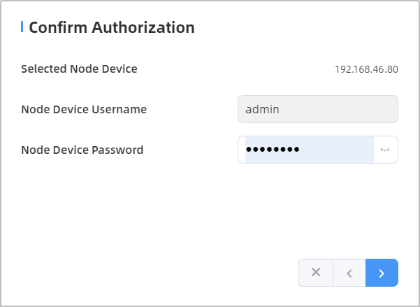
- Enter
the login password of the node device and click . The Bind the
Node Device page is displayed.
- To select a node device manually:
Bind Node Devices to Master Device
- Select Frame Overlapping or Frame
Non-overlapping stitching connection as needed.
Stitch Method Description Illustration Frame Non-overlapping Device coverage does not require overlapping areas; only the areas of interest need to be covered. It is only available for firmware version 1.0.5 or later.
Illustration for frame non-overlapping 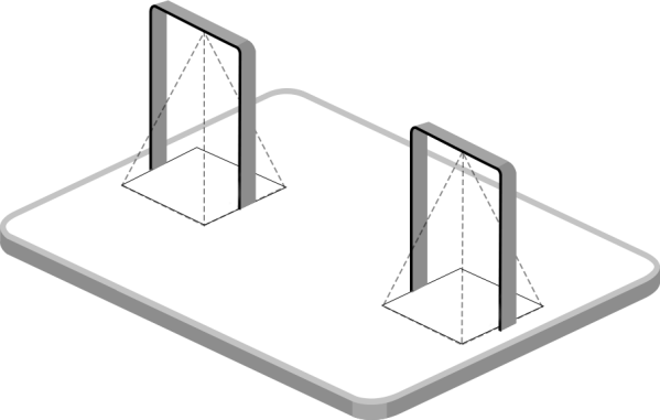
Frame Overlapping Device coverage requires overlapping areas to ensure complete tracking of targets. Illustration for frame overlapping 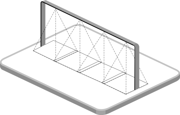
- If Frame Overlapping is
selected, follow the steps below:
- In the
Installation Height area, enter the
installation height of the node device or click
Detect to automatically measure the
installation height.
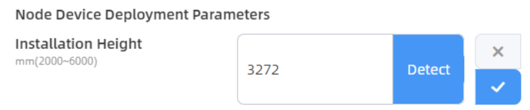
- Click IP addresses on
the right to access the previews of the stitched devices
and select the device sharing overlapping coverage areas
with this node device.
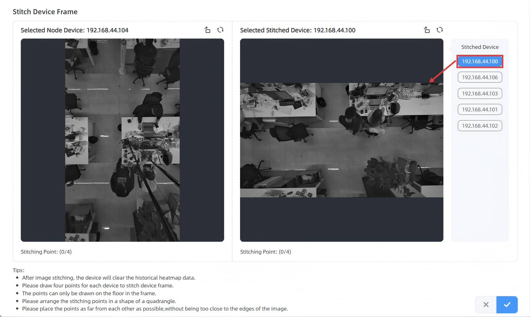
- On both device previews,
define the overlapping coverage areas by mark four
calibration points to form a quadrilateral. Then the
system automatically performs image stitching based on
these points.Tip: The overlapping area should be positioned in locations with minimal target traffic. It is recommended to use objects such as tiles, tables, or tape to mark the stitching points on the ground in the overlapping area.
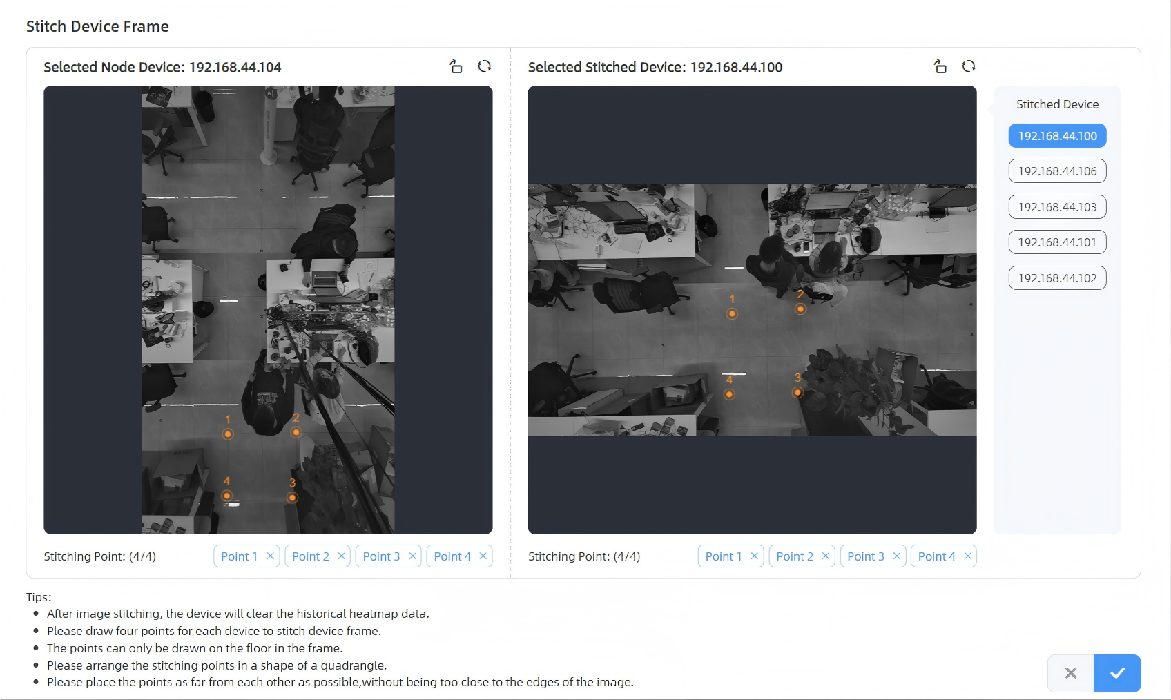
- (Optional) To modify the
calibration points, click
 to delete the corresponding
point
to delete the corresponding
point  and mark the point again.
 - Click to save the
configuration. The node device is listed in the
Multi-Device List. The following figure shows the
effect after the two devices are stitched.
- In the
Installation Height area, enter the
installation height of the node device or click
Detect to automatically measure the
installation height.
- If Frame Non-overlapping
is selected, follow the steps below:
- In the Installation
Height area, enter the installation height of
the node device or click Detect to automatically
measure the installation height. Configure the image
rotation angle relative to the master device.
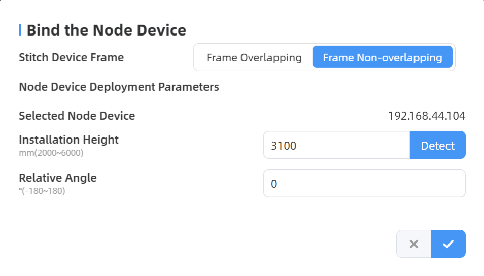
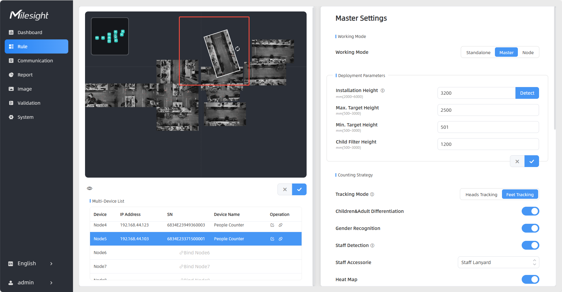
- Click to save the configuration. The
node device is listed in the Multi-Device List. The
following figure shows the effect after the two devices are
stitched.
- (Optional) Users can
optionally adjust the position of the node device
through the preview screen.
- In the Installation
Height area, enter the installation height of
the node device or click Detect to automatically
measure the installation height. Configure the image
rotation angle relative to the master device.
- If Frame Overlapping is
selected, follow the steps below:
- To add more devices,
follow steps 1 to 5 to stitch them sequentially. A small map in the
upper left part of the preview shows the positions of the stitched
devices.
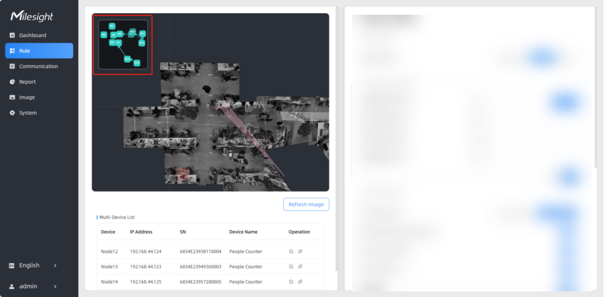
- (Optional) To disconnect
a node device, click
 in the corresponding Operation area.