5.3.4.1 Configure Installation Parameters
This section describes the settings related to the wirings.
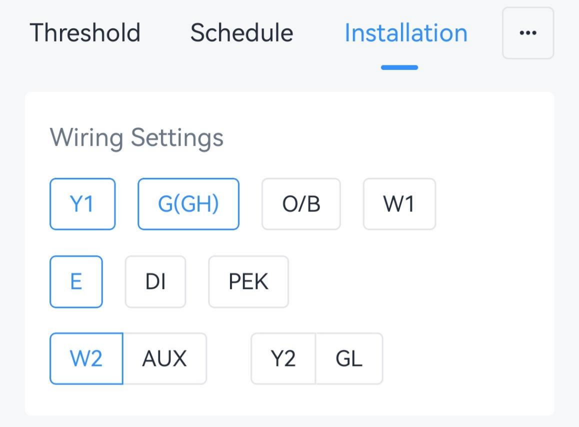
Wiring Settings
The wiring settings are used to control the software state of the relays and define the supported functions.
- On the homepage of ToolBox, click Setting to enter the Setting page.
- On the top bar, select Device tab.

- On the Installation page, enable the wire
terminals that match the wirings during the installation.
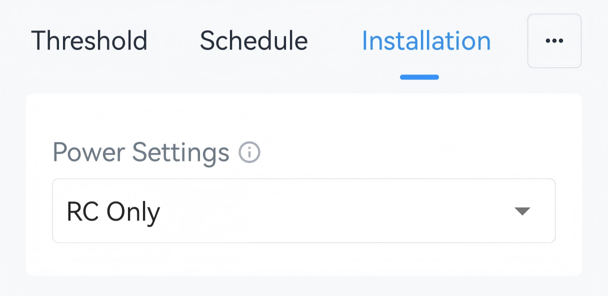
- Select the Power Setting as RC Only or RC&RH the same as the
settings during the installation.
- Select the options according to the HVAC system.
Parameter Wire Description Reversing Valve O/B Switch the O/B mode of a heat pump or PTAC. Energize on Cool: O/B relay closed=cool (default)
Energize on Heat: O/B relay closed=heatHeating System W1/W2/AUX/E+G Select a furnace or boiler. Fan Control during Heating Select Thermostat or Furnace/Boiler. - Click Write in the lower right corner, and
put the NFC detection area of the phone close to the NFC antenna of device.
If the configuration succeeds, the following page is displayed.

- JSON Command: wires, reversing_valve, fan_control_during_heating
- BACnet: Reversing Valve
- Raw Hex Command: Wiring Settings, Reversing Valve, Fan Control during Heating
Result
| Control Stage | Used Relay in Conventional System | Used Relay in Heat Pumps/PTAC |
|---|---|---|
| Stage-1 Cool | Y1 | Y1 |
| Stage-2 Cool | Y2 | Y2 |
| Stage-1 Heat | W1 | Y1 (+O/B) |
| Stage-2 Heat | W2 | Y2 (+O/B) |
| Stage-3 Heat | / | W1 |
| Stage-4 Heat | / | W2 |
Custom Temperature Control Stage
The thermostat can customize the used relays for every stage if the default settings do not match your requirements.
Prerequisites: Wiring Settings is configured.
- On the homepage of ToolBox, click Setting to enter the Setting page.
- On the top bar, select Device tab.
- On the Installation page, enable Custom Temperature Control
Stage.
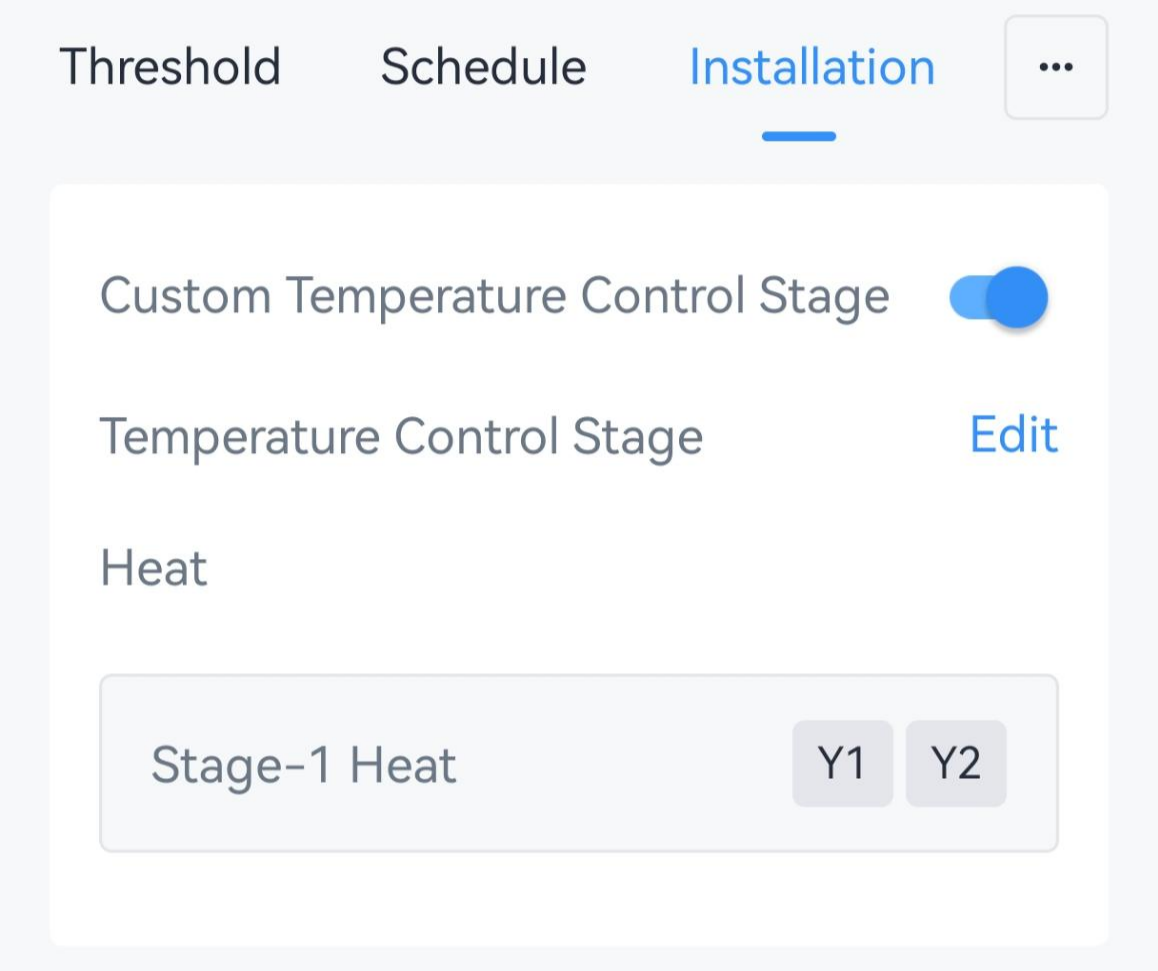
- Click Edit to navigate to the control stage page.
- Select the temperature control mode on the top bar, then click Add to
add the supported control stages, and select the relay for every stage. The
thermostat supports up to five heating stages, three cooling stages and one
EM heat stage.
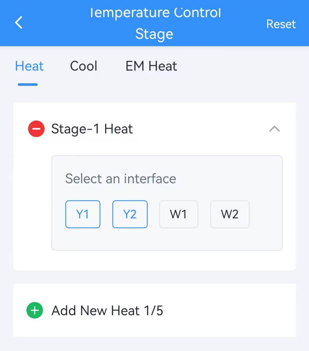
- Click Save.
- Click Write in the lower right corner, and
put the NFC detection area of the phone close to the NFC antenna of device.
If the configuration succeeds, the following page is displayed.
- JSON Command: custom_wiring_mode
- Raw Hex Command: Custom Temperature Control Stage Setting
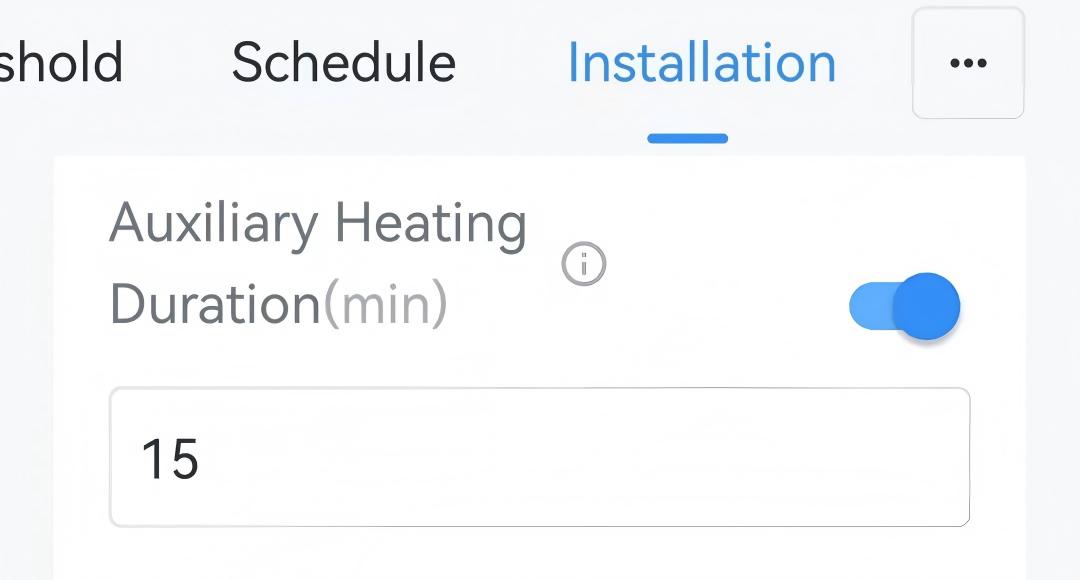
Auxiliary Heating Duration
The device supports limiting the auxiliary heating time to save energy.
Prerequisites: AUX is selected in Wiring Settings.
- On the homepage of ToolBox, click Setting to enter the Setting page.
- On the top bar, select Device tab.
- On the Installation page, enable Auxiliary Heating Duration and
configure the duration value.
- Click Write in the lower right corner, and
put the NFC detection area of the phone close to the NFC antenna of device.
If the configuration succeeds, the following page is displayed.
- Result
- When current temperature does not reach the target temperature even after heating for the auxiliary heating duration, report an Auxiliary Heating Timeout Alarm packet and switch back to lower stage heating mode.
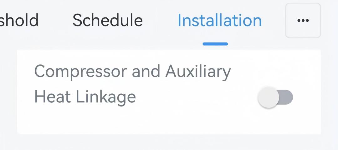
Compressor and Auxiliary Heat Linkage
| Heating Stage | 1-stage | 2-stage | 3-stage | 4-stage |
|---|---|---|---|---|
| Disable linkage | Y1+O/B | Y2+O/B | W1 | W2 |
| Enable linkage | Y1+O/B | Y2+O/B | Y2+O/B+AUX | W1 |
Prerequisites: Custom Temperature Control Stage is disabled, and Y1/Y2 + O/B + AUX are selected in Wiring settings.
- On the homepage of ToolBox, click Setting to enter the Setting page.
- On the top bar, select Device tab.
- On the Installation page, enable Compressor and
Auxiliary Heat Linkage.
- Click Write in the lower right corner, and
put the NFC detection area of the phone close to the NFC antenna of device.
If the configuration succeeds, the following page is displayed.
- JSON Command: compressor_aux_combine_enable
- Raw Hex Command: Compressor and Auxiliary Heat Linkage
Emergency Heating Duration
The device supports limiting the emergency heating time to save energy.
Prerequisites: E is selected in Wiring Settings.
- On the homepage of ToolBox, click Setting to enter the Setting page.
- On the top bar, select Device tab.
- On the Installation page, enable Emergency Heating Duration
and configure the duration value.

- Click Write in the lower right corner, and
put the NFC detection area of the phone close to the NFC antenna of device.
If the configuration succeeds, the following page is displayed.
- Result
- When the device operates in EM heat for longer than the duration, report an Emergency Heating Timeout Alarm packet and switch back to normal heat mode.
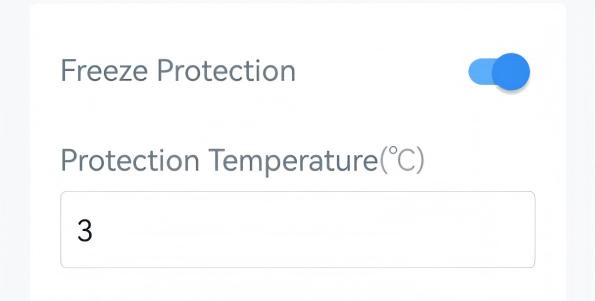
Freeze Protection
The device supports switching to EM Heat or Heat system to avoid freezing when detecting that the ambient temperature is too low. This feature takes effect even when the system is off.
Prerequisites: Heat or EM Heat is supported. If both are supported, EM Heat will be used first.
- On the homepage of ToolBox, click Setting to enter the Setting page.
- On the top bar, select Device tab.
- On the Installation page, enable Freeze Protection and
configure the protection temperature.
- Click Write in the lower right corner, and
put the NFC detection area of the phone close to the NFC antenna of device.
If the configuration succeeds, the following page is displayed.
- JSON Command: freeze_protection_config
- Raw Hex Command: Freeze Protection
- Result
- When the device detects that the ambient temperature is lower than
protection temperature, it sends a freeze protection trigger packet and
starts EM heat.
When the device detects that the ambient temperature is higher than freeze protection temperature, it sends a freeze protection release packet and switch to the previous status.
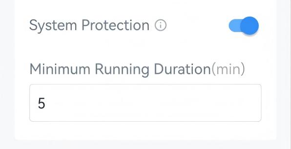
System Protection
Prerequisites: Either Y1/Y2/W1/ W2/AUX/E/ G is selected in Wiring Settings.
- On the homepage of ToolBox, click Setting to enter the Setting page.
- On the top bar, select Device tab.
- On the Installation page, enable System Protection and
configure the minimum running duration.
- Click Write in the lower right corner, and
put the NFC detection area of the phone close to the NFC antenna of device.
If the configuration succeeds, the following page is displayed.
- JSON Command: system_protect_config
- Raw Hex Command: System Protection
Y2/W2 Auxiliary Mode
By default, Y2 and W2 work in standalone mode. The device supports switching Y2 or W2 to auxiliary mode. Example:
| Heating Stage | 1-stage | 2-stage | 3-stage | 4-stage |
|---|---|---|---|---|
| Y2/W2 - standalone | Y1 (+O/B) | Y2 (+O/B) | W1 | W2 |
| Y2 - auxiliary mode | Y1 (+O/B) | Y1 + Y2 (+O/B) | W1 | W2 |
| W2 - auxiliary mode | Y1 (+O/B) | Y2 (+O/B) | W1 | W1 + W2 |
| Y2 and W2 - auxiliary mode | Y1 (+O/B) | Y1 + Y2 (+O/B) | W1 | W1 + W2 |
Prerequisites: Custom Temperature Control Stage is disabled, and Y2 or W2 is selected in Wiring Settings.
- JSON Command: aux_control_config
- Raw Hex Command: W2/Y2 Auxiliary Mode