Downlink Command
This chapter describes the downlink commands for device configuration and control. The downlink application port is 85 by default.
Basic Settings
| Item | Channel | Type | Byte | Description | ||||||||
|---|---|---|---|---|---|---|---|---|---|---|---|---|
| Report Interval | ff | 03 | 2 | UINT16, Unit: s | ||||||||
| Reboot | ff | 10 | 1 | ff | ||||||||
| Data Storage | ff | 68 | 1 | 00: Disable, 01: Enable | ||||||||
| Data Retransmission | ff | 69 | 1 | 00: Disable, 01: Enable | ||||||||
| Data Retransmission Interval | f9 | 0d | 2 | UINT16, Unit: s, Range: 30~1200, Default: 600 | ||||||||
| UTC Time Zone | ff | bd | 2 | INT16/60 | ||||||||
| Sync Time with LNS | ff | 4a | 1 | 00 | ||||||||
| Daylight Saving Time | f9 | 72 | 9 |
Byte 1:
Byte 2-5: Start time, Month (1B)+Week&Day (1B) + Minute Time (2B) Byte 6-9: End time Week&Day:
|
||||||||
| Enquiry Periodic Report | ff | 28 | 1 | ff | ||||||||
| Rejoin the Network | ff | 04 | 1 | ff |
- Example:
-
- Reboot the device.
ff10ff - Set report interval as 20 minutes.
ff03b004 Channel Type Value ff 03 b004=>04b0=1200s=20 minutes - Set time zone as UTC-4.
ffbd10ff Channel Type Value ff bd 10 ff => ff 10 = -240/60=-4 - Set DST time: start time is last Sunday 1:00 of March, end time is
last Sunday 1:00 of October, and bias is 1h (60 minutes).
f972bc03573c000a573c00 Channel Type Value f9 72 bc=>1 0111100 =>1=Enable, 0111100=60 minutes
Start time: 03=>March, 57=>last (5) Sunday(7), 3c 00 =>00 3c=60 minutes =1:00End time: 0a=>10=October, 57=>last (5) Sunday(7), 3c 00 =>00 3c=60 minutes =1:00
- Reboot the device.
RS485 Settings
| Item | Channel | Type | Byte | Description |
|---|---|---|---|---|
| Serial Settings | f9 | 78 | 7 | Byte 1-4: Baud rate, options:
1200, 2400, 4800, 9600, 19200, 38400, 57600, 115200 Byte 5: Data Bit, options: 07, 08, 09 Byte 6: Stop Bit, 01=1, 02=2, 03=1.5 Byte 7: Parity, 00=None, 01=Even, 02=Odd |
| Modbus Settings | f9 | 79 | 7 | Byte 1-2: Execution interval,
Unit: ms, Range: 10-1000 Byte 3-4: Max Resp Time, Unit: ms, Range: 10-60000 Byte 5: Max Retry Times, Range: 0-5 Byte 6: 00=Disable pass-through, 10=Active Pass-through, 11=Two-way Pass-through Byte 7: Pass-through port, range: 2-84, 86-223 |
| Enquiry RS485 Settings | f9 | 7a | 1 | 00=Serial Settings, 01=Modbus Settings |
- Example:
-
- Serial settings: baud rate is 9600, data bit is 8, stop bit is 1, no
parity.
f97880250000080100 Channel Type Value f9 78 Baud rate: 80 25 00 00=>00 00 25 80=9600 Data bit: 08=8
Stop bit: 01=1
Parity: 00=None
- Modbus settings: execution interval is 50ms, max resp time is
60000ms, max retry time is 3, enable Active pass-through and set the
port as 5.
f979320060ea031005 Channel Type Value f9 79 Execution interval: 32 00=>00 32=50ms Max Resp Time: 60 ea => ea 60=60000ms
Max Retry Time: 03=3
10=Active Pass-through
Pass-through port: 05=5
- Enquire serial settings.
Reply:f97a00 Channel Type Value f9 7a 00=Enquiry Serial Settings f87a0000 f97880250000080100 Channel Type Value f8 7a 00=Serial Settings, 00=Enquire Success f9 78 Baud rate: 80 25 00 00=>00 00 25 80=9600 Data bit: 08=8, Stop bit: 01=1, Parity: 00=None
- Serial settings: baud rate is 9600, data bit is 8, stop bit is 1, no
parity.
Modbus Channel Settings
| Item | Channel | Type | Byte | Description |
|---|---|---|---|---|
|
Add/Configure Modbus Channel |
ff | ef | 7 |
01+ Channel ID (1B)+Slave ID (1B) + Address (2B) + Data Type (1B) + Quantity & Sign (1B) Quantity & Sign: bit4: 1=signed, 0=unsigned (only work with Holding register int or Input register int types) bit3-bit0: Registers number, range: 1-2 |
|
Delete Modbus Channel |
ff | ef | 2 |
00+Channel ID (1B) |
|
Mobus Channel Name |
ff | ef | 4-19 |
02+Channel ID (1B) + Name Length (1B) + Name (Mutable) |
- Channel ID:
- The channel ID in downlink commands is different from uplinks:
Channel ID Description 01 RS485 (Modbus Master) Channel 1 02 RS485 (Modbus Master) Channel 2 ... ... 1f RS485 (Modbus Master) Channel 31 20 RS485 (Modbus Master) Channel 32
- Data Type:
-
Code Data Type 00 Coil 01 Discrete 02 Input16_AB 03 Input16_BA 04 Input32_ABCD 05 Input32_BADC 06 Input32_CDAB 07 Input32_DCBA 08 Input32_AB 09 Input32_CD 0a Input_float_ABCD 0b Input_float_BADC 0c Input_float_CDAB 0d Input_float_DCBA 0e Hold16_AB 0f Hold16_BA 10 Hold32_ABCD 11 Hold32_BADC 12 Hold32_CDAB 13 Hold32_DCBA 14 Hold32_AB 15 Hold32_CD 16 Hold_float_ABCD 17 Hold_float_BADC 18 Hold_float_CDAB 19 Hold_float_DCBA 1a Input_double_ABCDEFGH 1b Input_double_GHEFCDAB 1c Input_double_BADCFEHG 1d Input_double_HGFEDCBA 1e Input64_ABCDEFGH 1f Input64_GHEFCDAB 20 Input64_BADCFEHG 21 Input64_HGFEDCBA 22 Hold_double_ABCDEFGH 23 Hold_double_GHEFCDAB 24 Hold_double_BADCFEHG 25 Hold_double_HGFEDCBA 26 Hold64_ABCDEFGH 27 Hold64_GHEFCDAB 28 Hold64_BADCFEHG 29 Hold64_HGFEDCBA
- Example:
-
- Add a Modbus channel 1: a register, slave ID is 1, address is 1,
type is input_float_ABCD.

ffef 010101ffff0a01 Channel
Type
Value
ff ef Channel: 01=Channel 1 Slave ID: 01
Address: ff ff =65535
Type: 0a = Input_float_ABCD
01=one register - Set name of Modbus channel6 as “test6”.
ff ef 02 06 05 7465737436 Channel
Type
Value
ff ef Channel: 06=Channel 6
Name length: 05=5 Bytes
Hex to ASCii: 74 65 73 74 36 => t e s t 6
- Add a Modbus channel 1: a register, slave ID is 1, address is 1,
type is input_float_ABCD.
Rule Settings
| Item | Channel | Type | Byte | Description |
|---|---|---|---|---|
| Rule Status | f9 | 76 | 3 |
Byte 1-2: 1=enable configuration for per bit (rule) Byte 3: 01 = Enable, 02 = Disable, 03= Delete |
| Enquire Rule Settings | f9 | 77 | 1 |
Rule ID, Range: 1~16, the reply content is the same as the configured command |
| Item | Channel | Type | Byte | Description | |||||||||||||||||||||||||
|---|---|---|---|---|---|---|---|---|---|---|---|---|---|---|---|---|---|---|---|---|---|---|---|---|---|---|---|---|---|
| Time | f9 | 7d | 9 | Byte
1:
Byte 2: 11 Byte 3: Repeat mode, 00=weekly, 01=monthly Byte 4-7: Repeat
weekday or month day, 1=Enable, 0=Disable for per bit Byte 8: Hour, range: 0-23
Byte 9: Minute, range: 0-59 |
|||||||||||||||||||||||||
| Channel | f9 | 7d | 20 | Byte
1: Byte 2:
12
Byte 3: Channel ID, Range: 1-32 For threshold alarm: Byte
4: Byte 5-8: Continue time, UINT32, Unit:
ms, Range: 0-86400000
Byte 9-12: Lock time, UINT32, Unit: ms, Range: 0-86400000 Byte 13-16: Minimum threshold, Float32 Byte 17-20: Maximum threshold, Float32 For change alarm: Byte 4: 06=Change without time, 07=Change with time interval Byte 5-12: All 0Byte 13-16: Value change time interval, UINT32, Unit: ms, Range: 0-86400000 Byte 17-20: Maximum threshold, Float32 |
|||||||||||||||||||||||||
| Received a command via the RS485 interface | f9 | 7d | 5-51 | Byte
1: Byte 2:
13
Byte 3: Message Length, Range: 2-48 Byte 4-N: Message Content (Hex to ASCii) |
|||||||||||||||||||||||||
| Received a server message | f9 | 7d | 5-51 | Byte
1: Byte 2:
14
Byte 3: Message Length, Range: 2-48 Byte 4-N: Message Content (Hex to ASCii), only letter, number, comma, period, separator and exclamation mark are allowed |
|||||||||||||||||||||||||
| Received a D2D control command | f9 | 7d | 5 | Byte
1: Byte 2:
15
Byte 3-4: D2D Command Byte 5: Designed state, 00=Disable, 01=On, 02=Off |
|||||||||||||||||||||||||
| Device Restart | f9 | 7d | 2 | Byte
1: Byte 2:
16
|
| Item | Channel | Type | Byte | Description | ||||
|---|---|---|---|---|---|---|---|---|
| No Action | f9 | 7d | 2 | Byte
1: Byte 2:
90=Action 1, a0=Action 2, b0=Action 3
|
||||
| Send a server message | f9 | 7d | 8-55 | Byte
1: Byte 2:
91=Action 1, a1=Action 2, b1=Action 3
Byte 3-6: Delay time, UINT32, Unit: ms, Range: 0-86400000 Byte 7: Message Length, Range: 1-48 Byte 8-N: Message Content (Hex to ASCii), only letter, number, comma, period, separator and exclamation mark are allowed |
||||
| Send a D2D control command | f9 | 7d | 8 | Byte
1: Byte 2:
92=Action 1, a2=Action 2, b2=Action 3
Byte 3-6: Delay time, UINT32, Unit: ms, Range: 0-86400000 Byte 7-8: D2D Command |
||||
| Send a command via the RS485 interface | f9 | 7d | 9-55 | Byte
1: Byte 2:
93=Action 1, a3=Action 2, b3=Action 3
Byte 3-6: Delay time, UINT32, Unit: ms, Range: 0-86400000 Byte 7: Message Length, Range: 2-48 Byte 8-N: Message Content (Hex to ASCii) |
||||
| Upload data package | f9 | 7d | 6 | Byte
1: Byte 2:
94=Action 1, a4=Action 2, b4=Action 3
Byte 3-6: Delay time, UINT32, Unit: ms, Range: 0-86400000 |
||||
| Upload alarm packet | f9 | 7d | 7 | Byte
1: Byte 2:
95=Action 1, a5=Action 2, b5=Action 3
Byte 3-6: Delay time, UINT32, Unit: ms, Range: 0-86400000 Byte 7: Threshold release packet upload, 00=Disable,01=Enable |
||||
| Device Restart | f9 | 7d | 6 | Byte
1: Byte 2:
96=Action 1, a6=Action 2, b6=Action 3
Byte 3-6: Delay time, UINT32, Unit: ms, Range: 0-86400000 |
| Channel | Type | Command Content | Reply |
|---|---|---|---|
| f8 | 7d | The same as command | 00: Success 02: Out of range 10: Illegal condition 11: Illegal condition parameter 12: Illegal action1 parameter 13: Illegal action2 parameter 14: Illegal action3 parameter 15: Condition conflicts with action1 configuration 16: Condition conflicts with action2 configuration 17: Condition conflicts with action3 configuration 18: Action 1 and Action 2 are configured repeatedly 19: Action 1 and Action 3 are configured repeatedly 1a: Action 2 and Action 3 are configured repeatedly |
- Example:
-
- Enable Rule 1 and Rule 16.
f976018001 Channel Type Value f9 76 01 80 => 80 01=Bit15 and Bit 0 is 1=Rule 16 and Rule 1 01=Enable
- Add/Configure Rule 1 as below:
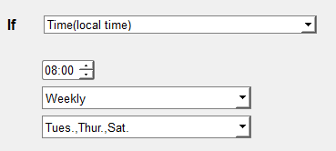
f97d8111002a0000000805 Channel Type Description f9 7d 81=>1 0000001=Rule1 enable 11=Time Condition, 00=Weekly
2a000000=>00 00 00 2a = 0010 1010 =every Tues., Thurs., and Sat.
0805=8:05
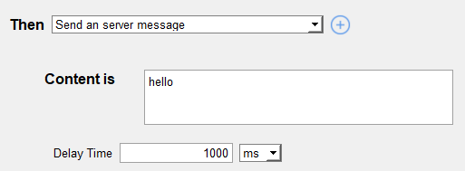
f97d8191e80300000568656c6c6f Channel Type Description f9 7d 81=1 0000001= Rule1 enable 91= Action 1: Send a server message
Delay time: e8 03 00 00 => 00 00 03 e8 = 1000ms
Message length: 05 => 5
68 65 6c 6c 6f=> hello (Hex to ASCii)
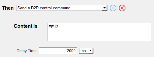
f97d81a2d007000012fe Channel Type Description f9 7d 81=1 0000001= Rule1 enable a2= Action 2: Send a D2D control command
Delay time: d0 07 00 00=> 00 00 07 d0 = 2000ms
D2D command: 12fe => fe12
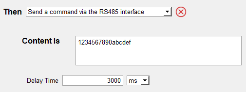
f97d81b3b80b00001031323334353637383930616263646566 Channel Type Description f9 7d 81=1 0000001= Rule1 enable b3= Third Action 3: Send a command via the RS485 interface
Delay time: b8 0b 00 00 =>00 00 0b b8=3000ms
Message length: 10 =>16
31323334353637383930616263646566 => 1234567890abcdef (Hex to ASCii)
- Enquire rule 2 configuration.
Reply:f97702 Channel Type Value f9 77 02=Rule 2 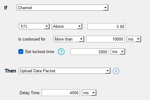
f97d8212041310270000881300000000000000a040
f97d8294a00f0000 f97d82a0f97d82b0
Channel Type Value f9 7d 82=1 0000010= Rule2 enable 12=Channel Condition, 04=Modbus Channel 4
13=>Above, is more than
Continue time: 10 27 00 00 =>00 00 27 10=10000ms
Lock time: 88 13 00 00 => 00 00 13 88= 5000ms
Minimum threshold: 00 00 00 00
Maximum threshold: 00 00 a0 40=> 40 a0 00 00=5 (Hex to Float32)
f9 7d 82=1 0000010= Rule2 enable 94= Action 1: Upload a data package
Delay time: a0 0f 00 00=>00 00 0f a0=4000ms
f9 7d 82=1 0000010= Rule2 enable a0=Action 2: No Action
f9 7d 82=1 0000010= Rule2 enable b0= Action 3: No action
- Enable Rule 1 and Rule 16.