Traffic Detection
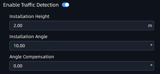
Step1: Click ![]() button to enable Traffic Detection and enter the
camera installation information;
button to enable Traffic Detection and enter the
camera installation information;
|
Parameters |
Function Introduction |
|---|---|
|
Click the button to enable Traffic Detection function. |
|
|
Installation Height |
Fill in the installation height according to the actual installation height of the camera. |
|
Installation Angle |
Fill in the installation height according to the actual installation angle between the camera's field of view and the horizontal. |
|
Angle Compensation |
Support angle compensation range: -30°~30°, default 0°. Angle compensation is mainly used as horizontal angle compensation, such as the radar cannot be installed in the middle of the road. In order to detect data more accurate, the angle between the installation position and the road can be compensated and corrected. |
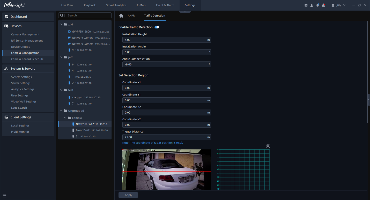
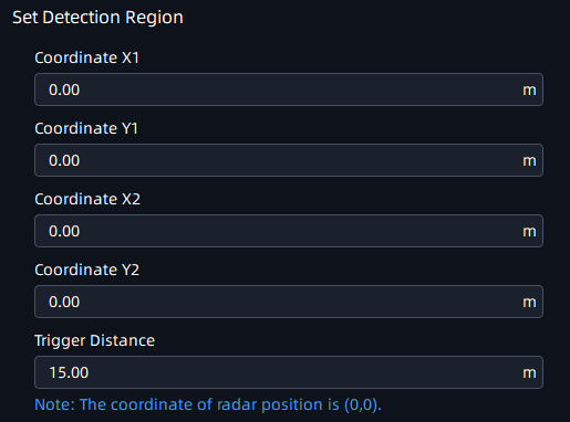
Step2: Set Detection Region. Configure the radar detection area on the basis of the successful saving of the LPR detection area settings;
The user needs to measure the actual spatial position coordinates of the two coordinate points (relative to the Radar AI LPR Camera position). e.g.: You can adjust the position of P1, P2 by mouse, as shown in the figure below, move the P1 point to the white traffic line in the lower right corner, then you need to measure the horizontal and vertical distance from the camera to the actual position corresponding to the P1 point. Similarly, please complete the distance measurement of point P2.
We recommend that you move the P1 point marker to a more Obvious target (such as trees or other landmarks) , so you can measure the distance easier.
The Radar detection area is a rectangle with diagonal lines in the two coordinate points;
|
Parameters |
Function Introduction |
|---|---|
|
Coordinate X1&Y1 |
X and Y axis parameters of P1 coordinates. |
|
Coordinate X2&Y2 |
X and Y axis parameters of P2 coordinates. |
Step3: Set LPR Detection Region Calibration.
To match LPR data, please configure LPR detection region calibration after radar detection. The calibration of the LPR detection area is mainly to match the space coordinates. The number of this configuration item shows the corresponding number according to the number of the LPR detection area. The data filled in is based on the corresponding trajectory map on the right when the target vehicle enters the area to find the target and fill in the X value shown above. To match LPR data, please configure LPR detection region calibration after radar detection.
For example, after you have drawn 3 detection areas, you can find the coordinate information corresponding to the targets in the three detection areas from the radar coordinates. You only need to fill in this coordinate information;
Step4: Schedule Settings. Set the effective time of traffic detection.
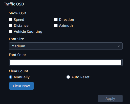
Step5: Traffic OSD Settings. Customers can choose the information that needs to be displayed in Live Video and the display format, such as color, size, etc.
|
Parameters |
Function Introduction |
|---|---|
|
Show OSD |
Users can choose the information they want to display in Live Video. |
|
Font Size&Font Color |
The font size and color of the OSD display, the default size is Medium. |
|
Manually |
Manually reset the vehicle count. |
|
Auto Reset |
It is used to automatically clear the vehicle count at regular intervals (Just reset the OSD count for Live Video). |