Master Device Setting
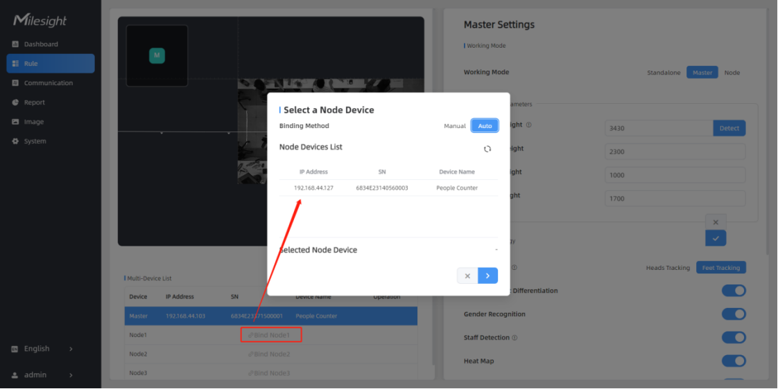
Step 1: Go to the master device web GUI, then click Bind Node in the Multi-Device List.
Manual: You can add a node device by the IP address, HTTP Port, Username or Password.
Auto: The device will use multicast protocol to search for the unbound node devices under the same local network.
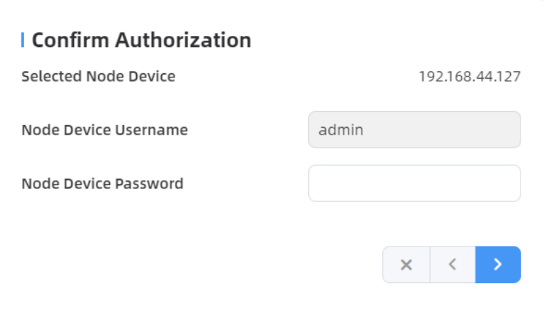
Step 2: Select the node device and type the login password of the node device.
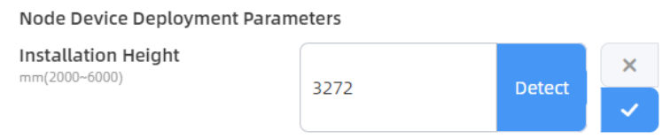
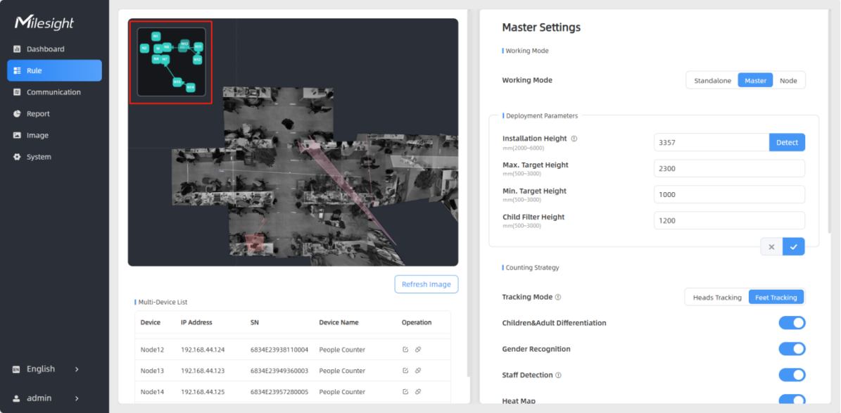
Step 3: Fill in the Installation Height of the node device and relative position information if these parameters are already measured. If not, save the default settings.
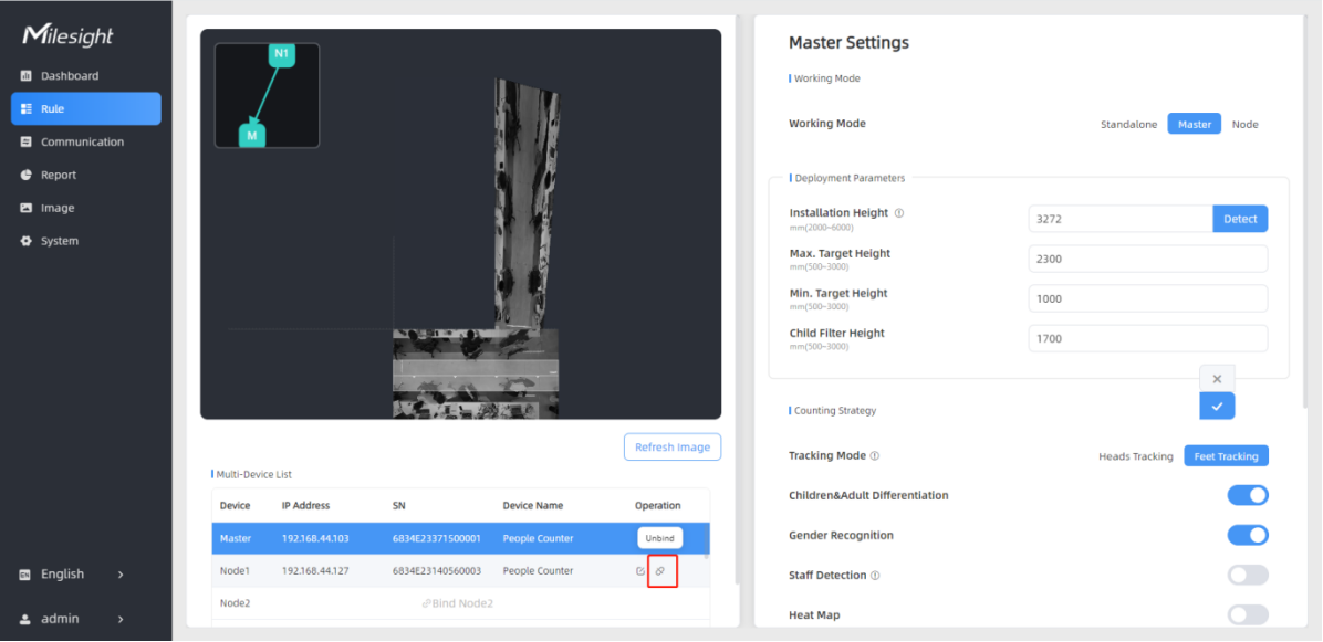
Click the IP address on the right to access the preview of the stitched device.
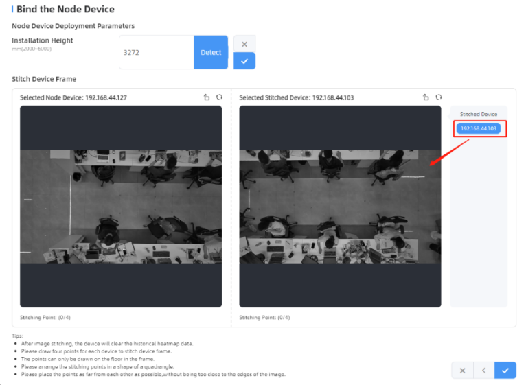
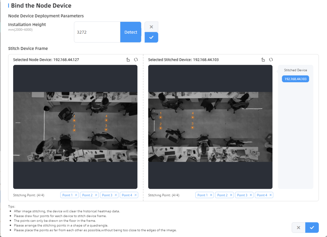
Click on the parts that need to be overlapped on both frames to form a quadrilateral.
It's recommended to place the overlapping area where detection targets rarely pass. If
modifications are needed, please delete the corresponding points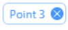 . Click
 ![]() to
complete the configuration.
to
complete the configuration.
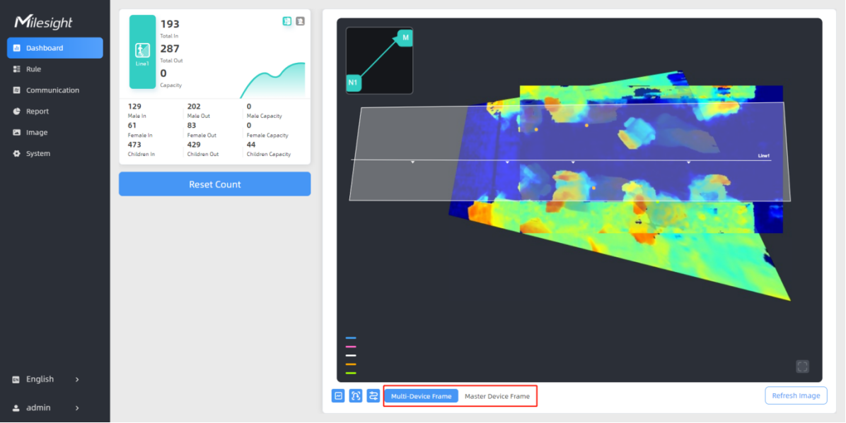
Below is the effect after stitching the two devices:
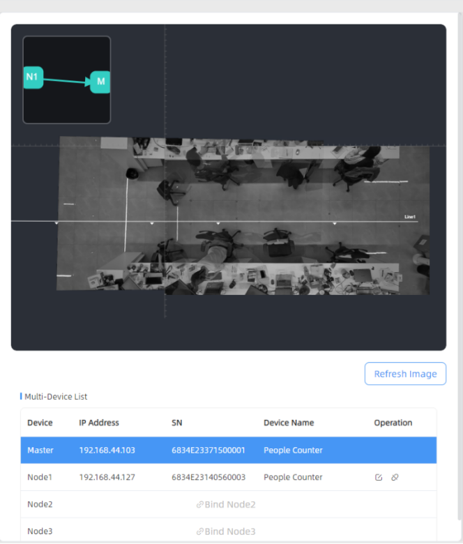
Step 4: For multiple devices, please follow step3 to stitch them sequentially. A small map in the upper left corner of the preview image shows the positions of the stitched devices.
Step 5: When all settings are completed, users can draw detection lines and even U-turn areas on the new stitching live view the same as standalone mode devices. The dashboard will automatically add two frames for viewing the stitching devices and the master device.
Step 6: Click Unbind to disconnect the node device if necessary.