LoRaWAN® Settings
This chapter describes how to configure the LoRaWAN® parameters for communication between the device and LoRaWAN® gateways.
- Configure Join Type and Frequency
- It is necessary to configure the join type and the frequency parameters to
establish communication with LoRaWAN® gateways.
Steps:
1. Go to Setting > Network > LoRaWAN page.
2. Select the Join Type as OTAA or ABP mode as needed.Note: OTAA is required if you connect the device to Milesight Development Platform.3. Configure the related Join Type parameters as needed. You can also use default values unless otherwise specified.- If OTAA is selected, configure the Application Key and
Rejoin Mode as needed.
Parameter Description Application Key Appkey for OTAA mode, default value: "Device EUI" + "Device EUI". Example: 24e124123456789024e1241234567890 Note: Please contact sales before purchase if you require random App Keys.Rejoin Mode Reporting interval≤35 mins: the device will send a specific number of LinkCheckReq MAC packets to the network server every reporting interval or every double reporting interval to validate connectivity; If there is no response, the device will re-join the network.
Reporting interval > 35 mins: the device will send a specific number of LinkCheckReq MAC packets to the network server every reporting interval to validate connectivity; If there is no response, the device will re-join the network.
When Rejoin Mode is enabled, enter a number in the Set the number of detection signals sent text box. The actual sending number is the configured number +1.
- If ABP is selected, configure Network Session Key,
Application Session Key and Device Address as needed. You can also
use default values unless otherwise specified.
Parameter Description Network Session Key Nwkskey for ABP mode, the default is 5572404C696E6B4C6F52613230313823. Application Session Key Appskey for ABP mode, the default is 5572404C696E6B4C6F52613230313823. Device Address DevAddr for ABP mode, default is the 5th to 12th digits of SN.
4. Select the Supported Frequency the same as the LoRaWAN® gateway and configure the related parameters. You can also use default values unless otherwise specified.- If the Supported Frequency is US915 or AU915, enter the
channel index(es) separated by commas.
Examples:
1, 40: Enabling Channel 1 and Channel 40
1-40: Enabling Channel 1 to Channel 40
1-40, 60: Enabling Channel 1 to Channel 40 and Channel 60
All: Enabling all channels
Null: All channels are disabled
Tip: Set the Channel Index to 8-15 when connecting to a Milesight LoRaWAN® gateway with default frequency settings.
- If the Supported Frequency is AS923, select a channel plan and enable the frequencies as needed.
- If the Supported Frequency is any option other than those listed above, enable the frequencies as needed.
- If OTAA is selected, configure the Application Key and
Rejoin Mode as needed.
- Configure Other LoRaWAN® Parameters
-
Steps:
1. Go to Setting > Network > LoRaWAN page.
2. Configure the parameters as needed. You can also use default values unless otherwise specified.Parameter Description Device EUI Unique ID of the device which can be found on the device. Note: please contact sales for device EUI list if you have many units.App EUI The default App EUI (join EUI) is 24E124C0002A0001. Application Port The port used for sending and receiving data, the default port is 85. LoRaWAN® Version V1.0.2 and V1.0.3 are available. Work Mode Class A (default) or Class C is optional. Class A: This mode is applicable when the device is powered by batteries, which can save the power.
Class C: This mode is applicable when the device is powered by an external power supply, enabling low-latency control.
Confirmed Mode If the device does not receive ACK packet from network server, it will resend data once.
ADR Mode Enable or disable network server to adjust Spreading Factor, Bandwidth an Tx Power to optimize data rates, airtime and energy consumption in the network. Spreading Factor If ADR mode is disabled, the device will send uplink data following this SF parameter. The higher the spreading factor, the longer the transmission distance, the slower the transmission speed and the more the consumption. Tx Power Tx power (transmit power) refers to the strength of the outgoing signal transmitted by the device. This is defined by LoRa alliance. RX2 Data Rate RX2 data rate to receive downlinks.
RX2 Frequency RX2 frequency to receive downlinks. Unit: Hz
Multicast Group Enable or disable the multicast groups to receive the multicast commands. This feature only works when the work mode is Class C. See Configure the Multicast Group for details.
- Configure the Multicast Group
-
The device supports setting up several multicast groups to receive multicast commands from the network server, then users can use this feature to control devices in bulk.
Note: This feature only works when the work mode is Class C.Steps:
1. Enable Multicast Group, and set unique multicast address and keys to distinguish other groups. You can also keep these settings by default.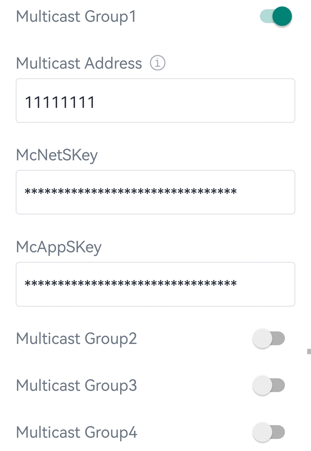
Parameter Description Multicast Address Unique 8-digit address to distinguish different multicast groups. Multicast McNetSkey 32-digit key. Default values:
Multicast Group 1: 5572404C696E6B4C6F52613230313823
Multicast Group 2: 5572404C696E6B4C6F52613230313824
Multicast Group 3: 5572404C696E6B4C6F52613230313825
Multicast Group 4: 5572404C696E6B4C6F52613230313826
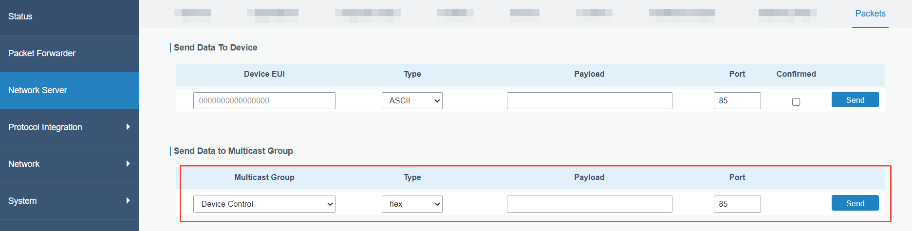
Multicast McAppSkey 2. Add a multicast group on the LoRaWAN® network server. Take Milesight gateway as example, go to Network Server > Multicast Groups to add a multicast group and configure the group according to the device settings.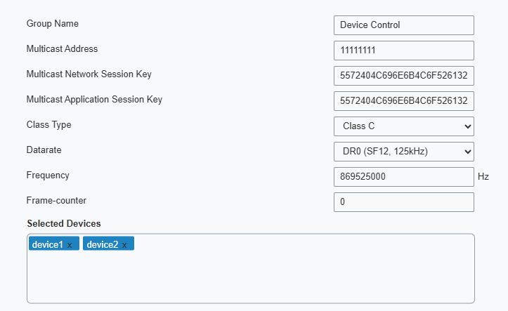 3. Go to Network Server > Packets, select the multicast group and fill in the downlink command, click Send. The network server will broadcast the command to devices that belong to this multicast group.Note: Ensure all devices' application ports are the same.