RS485 Settings
UC100 supports to set up communications with RS485 via two ways: Modbus channels or Modbus RS485 bridge LoRaWAN®.
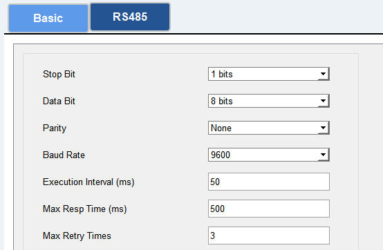
Basic Serial Settings
UC100 has one RS485 port for Modbus RTU device connection. The basic serial settings should be the same as RS485 terminal devices.
| Parameter | Description |
|---|---|
| Stop Bit |
1 bit/2 bit is available. |
|
Data Bit |
8 bit is available. |
|
Parity |
None, Odd and Even are available. |
|
Baud Rate |
1200/2400/4800/9600/19200/38400/57600/115200 are available. |
|
Execution Interval (ms) |
The execution interval between each Modbus channel command. |
|
Max Resp Time (ms) |
The maximum response time that the UC100 waits for the reply to the command. If it does not get a response after the max response time, it is determined that the command has timed out. |
|
Max Retry Times |
Set the maximum retry times after the device fails to read data from RS485 terminal devices. |
Modbus Channels
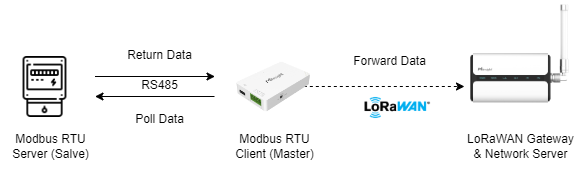
UC100 supports to work as a Modbus RTU Client (Master) to poll the data from the RS485 device and return the data to the network server.
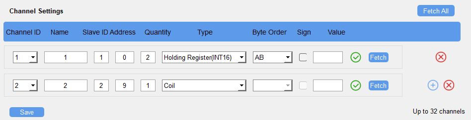
Click ![]() to add Modbus channels, then save configurations.
to add Modbus channels, then save configurations.
| Parameter | Description |
|---|---|
|
Channel ID |
Select the channel ID you want to configure from 32 channels. |
|
Name |
Customize the name to identify every Modbus channel. |
|
Slave ID |
Set a Modbus slave ID of a terminal device. |
|
Address |
The starting address for reading. |
|
Quantity |
Set the number of registers to read. It can be configured to 1 or 2. |
|
Type |
Select the data type of Modbus channels. |
|
Byte Order |
Set the Modbus data reading order if you configure the type as Input register or holding register. INT64/Double: ABCDEFGH, GHEFCDBA, BADCFEHG, HGFEDCBA INT32/Float: ABCD, CDBA, BADC, DCBA INT16: AB, BA |
|
Sign |
The tick indicates that the value has a plus or minus sign. |
|
Fetch |
Click to send a Modbus read command to test if the RS485 device
can reply with the correct values.
Note: Do not click frequently to avoid the fetch failure due to
the slow response of RS485 devices. Example: 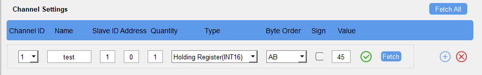 |
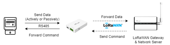
Modbus RS485 bridge LoRaWAN®
UC100 supports to work as a relay to set up the communication between the server and RS485 devices. There are two pass-through modes:
Active Pass-through: the network server can send any command to the RS485 device and the RS485 device can only react according to server commands.
Two-way Pass-through: not only can network server send any command to the RS485 device, but also the RS485 device supports transmitting the data to the network server actively.
When Two-way Pass-through is enabled, Modbus channels can’t be used and the corresponding IF-THEN command will not work.
| Parameter | Description |
|---|---|
|
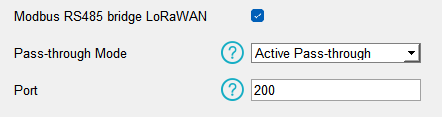
Modbus RS485 bridge LoRaWAN® |
Enable or disable the Modbus RS485 bridge LoRaWAN® feature. |
|
Pass-through Mode |
Select from Active Pass-through or Two-way Pass-through. |
|
Port |
The communication port between the RS485 device and the network server. Range: 2-84, 86-223. |