IO Device
This chapter describes how to configure the IO interfaces for terminal device connection.
Prerequisites
-
Refer to Wiring Diagrams to confirm that the IO devices are compatible with the gateway.
- Follow Terminal Device Wirings instructions to connect IO devices to the correct interfaces.
Steps
- On the left bar, select Data Service > Data
Acquisition page.
- On the top bar, select IO Device tab.
- Enable the required IO interface and check their
information.
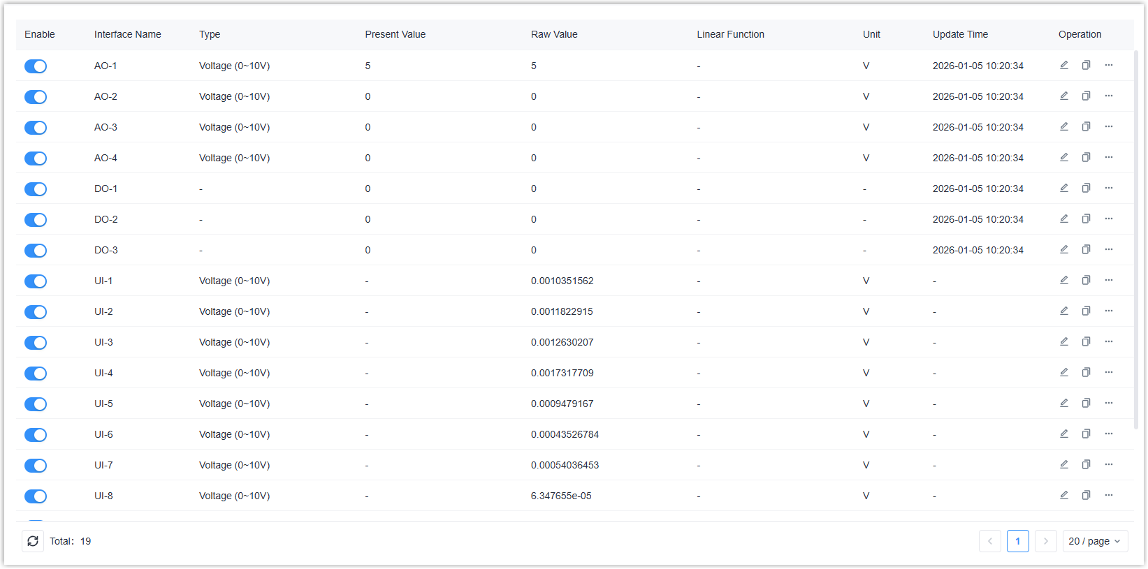
Parameter Description Enable Enable or disable the interface. Interface Name Display the interface type. Type Display the configured type of the interface. Present Value For input types, it displays the value after processing via Linear Function or Polarity Inversion; for output types, it displays the value sent by the user. Raw Value For input types, it displays the raw collected value; for output types, it displays the value after processing via Linear Function or Polarity Inversion. Linear Function When the type is not DI, Counter or DO, it displays the linear function formula. Unit When the type is not DI, Counter or DO, it displays the unit of the value. Update Time Displays the latest time the value was output or the input value was obtained. Operation  : Click to
configure the IO interface parameters.
: Click to
configure the IO interface parameters. : Copy the
parameters of the current interface to other
interfaces of the same type.
: Copy the
parameters of the current interface to other
interfaces of the same type. : Click to
perform test actions based on different interface
types.
: Click to
perform test actions based on different interface
types. - Click to configure the IO interface parameters
according to different interface types.
- For Analog Output (AO)
-
Parameter Description Enable Enable or disable this interface. Output Type Select the output type between Current (4-20mA) and Voltage (0-10V). CAUTION: Ensure the type matches the connected device; otherwise, it may damage the gateway or the connected device.Unit Select the output value unit. Output After Reboot Select the output value for after reboot. Keep Last Raw Value: Output the last raw value after reboot.
Custom Raw Value: Define a custom raw value to output.Description For noting this interface. Linear Function After enabled, the configured output value will be substituted into the function formula before being output. The formula: y=a*x+b(y: present value/configured value, x: raw value/real output value)
- For Digital Output (DO)
-
Parameter Description Enable Enable or disable this interface. Polarity Inversion Select the polarity inversion status. Normal: Open = 0, Close = 1
Reverse: Close = 0, Open = 1Output After Reboot Select the output value after reboot. Keep Last Value: Output the last value before reboot.
Closed/Open: Select the desired value to output.Description For noting this interface.
- For Digital Input (DI)
-
Parameter Description Enable Enable or disable this interface. Input Type Select the input type from Level Status or Counter. Description For noting this interface. Input Type is Level Status Filter Time The present value will update only when the changed level status persists for longer than this time. Polarity Inversion Select the polarity inversion status. Normal: Low Level = 0, High Level = 1
Reverse: High Level = 0, Low Level = 1Input Type is Counter Trigger Condition Select the triggering condition for incrementing he count value. Filter Time The count value will increment by 1 only when the changed level status persists for longer than this time. Trigger Count When the count value reaches this value, a packet will be reported to the MQTT broker.
- For Universal Input (UI)
-
Parameter Description Enable Enable or disable this interface. Input Type Select the input type among these options: Voltage (0-10V), Current (4-20mA), Resistance 1000Ω, Resistance 2000Ω, NTC 10K Type2, NTC 10K Type3, NTC 20K, Pt1000, Ni1000, DI. CAUTION: Ensure the type matches the connected device; otherwise, it may damage the gateway.Collection Interval Define the interval to collect data from the terminal device. Range: 1-86400 s. Description For noting this interface. Input Type is DI High-Level Threshold When the external voltage exceeds this threshold, the DI is determined to be at a high level. Range: 2-24V.
Low-Level Threshold When the external voltage is below this threshold, the DI is determined to be at a low level. Range: 0-2V. Polarity Inversion Select the polarity inversion status. Normal: Low Level = 0, High Level = 1
Reverse: High Level = 0, Low Level = 1Input Type is not DI Unit Select the input value unit. Linear Function After enabled, the collected value will be substituted into the function formula before display. The formula: y=a*x+b(y: present value, x: raw value/real collected value)
Single Lead Resistance For Pt1000 or Ni1000 sensors, enter the lead resistance value to prevent the leads from affecting accuracy.
- Click Save to save above settings.
- Click to take some actions to test the IO
interfaces.
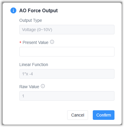
- For AO type, click Force Output to define a value to
output.
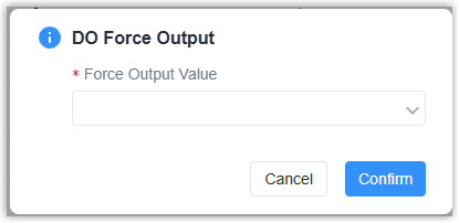
- For DO type, click Force Output to set the output status to
Closed or Open.
- For UI type, click Get Value to read the value immediately.
- For DI-Count type, click Reset to reset the count value.
- For AO type, click Force Output to define a value to
output.